558 AMD Geode™ LX Processors Data Book
GeodeLink™ Control Processor Register Descriptions
33234H
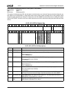
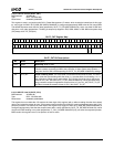
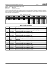
GLCP_DOTPLL Bit Descriptions
Bit Name Description
63:49 RSVD Reserved. Write as read.
48 DIV4 Divide by 4. When set, the PLL output is divided by 4 before clocking the logic. This bit
is intended for generating frequencies below the PLL spec limit of 15 MHz.
47 RSVD Reserved.
46:44 MDIV Input Clock Divisor. The DOTPLL M setting (resets to VGA timing).
43:36 NDIV Dot Clock PLL Divisor. The DOTPLL N setting (resets to VGA timing).
35:32 PDIV Post Scaler Divisor. The DOTPLL P setting (resets to VGA timing).
31:26 SWFLAGS Software Flags. Unlike in the GLCP_SYS_RSTPLL register (MSR 4C000014h), these
bits are reset to 0 by a soft reset to the chip. These bits are otherwise read/writable by
software. They are not reset by a DOTRESET (bit 0 of this register).
25 LOCK (RO) Lock (Read Only). Lock signal from the DOTCLK PLL.
24 HALFPIX Half Pixel. The DC and VP receive a half-frequency Dot clock while the VOP logic
receives the normal frequency determined by the MDIV, NDIV, PDIV settings. This fea-
ture enables 8-bit VOP of SD data at 27 MHz VOP clock (pixel rate only 13.5 MHz).
23:16 RSVD Reserved. Write as read.
15 BYPASS Dot PLL Bypass. This signal controls the bypass mode of the DOTCLK PLL. If this bit is
high, the DOTREF input clock directly drives the raw DOTCLK, bypassing the MDIV,
NDIV, and PDIV logic.
14 PD Power Down. This bit controls the power down mode of the DOTCLK PLL. It is active
high.
13 CAPEN Capacitor Enable. The CAPEN signal to the DOTPLL enables an external capacitor for
the loop filter.
0: An external capacitor is not used. Internal circuitry is used to stabilize the loop opera-
tion.
1: Enables the use of an external capacitor for the loop filter.
12:10 RSVD Reserved.
9:1 RSVD Reserved. Read/writable bits not currently used.
0 DOTRESET Dot Clock Reset. The reset pin to the Dot clock time blocks. The Dot reset is held active
when CHIP_RESET (MSR 4C000014h[0]) is high, but this bit resets to 0. It is recom-
mended that software set this bit when changing PLL settings and observe LOCK before
releasing this reset. Unlike the SYS_RSTPLL register, this bit is not required to be set
before the other bits in this register affect the PLL.


