AMD Geode™ LX Processors Data Book 241
Graphics Processor
33234H
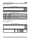
Where:
6.3.2 Channel 3
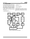
Channel 3 is an additional DMA channel (in addition to the
first two channels: source and destination) that can fetch
data from memory or receive it through host source writes.
This channel has all of the data conversion features built in
to perform rotational BLTs, color depth conversions, pallet-
ized color support (LUT lookups), 8x8 color pattern, and
patterned vector support. The data coming out of this DMA
pipeline can selectively be steered into the old source
channel or the old pattern channel, whichever is more nat-
ural for a given ROP. Note that not all data coming out of
this pipeline can be arbitrarily ROPed with other data (i.e.,
rotational BLT data can not be ROPed with any other chan-
nel, alpha data is expected to be used as input to the alpha
unit). The behavior of channel 3 is controlled through
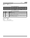
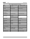
GP_CH3_MODE_STR (GP Memory Offset 64h). Channel
3 is also set up to be mostly independent from the other
two channels, so it calculates its own addresses and pixel
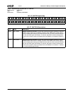
counters based on the GP_CH3_OFFSET and
GP_CH3_WIDHI (GP Memory Offset 60h and 68h respec-
tively). It is possible to set up this channel with a different
width and height than the destination (i.e., a rotation BLT
will have width and height swapped from the destination).
As long as the number of pixels to be fetched is the same
as the output, there should be no problem. If this channel
has too few pixels to complete the BLT and is not in host
source mode, the BLT will terminate when this channel has
fetched all of the requested data, and the underflow bit will
be set in GP_BLT_STATUS (GP Memory Offset 44h). If
this channel has pixels left when the BLT is complete, the
extra pixels are discarded and the overflow bit is set in
GP_BLT_STATUS.
Channel 3 has the ability to begin prefetching data for a
pending BLT before the active BLT has completed. The PE
bit in the GP_CH3_MODE_STR register (GP Memory Off-
set 64h[19]) can be set to allow prefetching for that BLT.
Prefetching can safely be set for any BLT that does not
require write data from the previous BLT as read data on
channel 3. The GP does no hazard checking to verify the
safety of the prefetch. This feature will incrementally
improve performance as it allows the GP to make use of
bus bandwidth that would otherwise have gone unused.
Prefetching has the lowest bus priority and is only done
opportunistically.
The X and Y bits (bits 29 and 28) in the
GP_CH3_MODE_STR register do not need to be pro-
grammed the same as the bits in the GP_BLT_MODE reg-
ister (GP Memory Offset 40h). If they are the same, the
result is a source copy. If both bits are programmed oppo-
site from the GP_BLT_MODE register, then the result is a
180° rotation. If only one bit is opposite, the result is a flip in
that direction.
When the current operation is a vector, channel 3 can gen-
erate byte enables to stylize the vector based upon the pro-
grammed pattern. Channel 3 cannot be used to generate
any pixel data while rendering vectors.
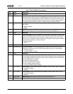
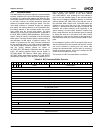
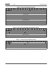
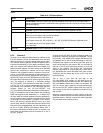
Table 6-12. Bit Descriptions
Name Description
WE Write Enable. One bit for each of the required DWORDs which follow in the command buffer. A
set bit indicates that the field is valid and should be updated in the GP. A clear bit indicates the field
should be skipped.
W Wrap Bit. If set, then return to the top of command buffer space after executing this buffer.
S Stall Bit. Execution of this command will be stalled until the GP’s pipeline is empty.
DTYPE Data Type. Type of data that follows:
000: Host source data to old host source channel
001: Host source data to new channel 3
010: Pattern data to GP_PAT_COLOR_2 - GP_PAT_COLOR5 (GP Memory Offset 20h-2Ch)
011: Write data for LUT/color pattern space
1xx: Reserved
DCOUNT DWORD Count. Number of DWORDs of data that follow.


