AMD Geode™ LX Processors Data Book 315
Display Controller Register Descriptions
33234H
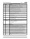
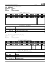
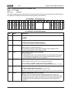
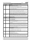
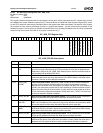
24 SIGE Signature Enable. Effective immediately.
0: CRC Signature is reset to 000001h and held (no capture).
1: CRC Logic captures the pixel data signature with each pixel clock beginning with the
next leading edge of vertical blank. Note that the CRC Logic treats each 24-bit pixel
value as an autonomous 24-bit value (RGB color components are not captured sepa-
rately in 8-bit signature registers).
23 SIG_SEL Signature Select. Effective immediately.
1: Causes the CRC signature to be generated based on data being fed into the graphics
scaling filter. This data stream does not include border/overscan pixels.
0: Clearing this bit allows bit 4 to select between the CRC calculation at the output of the
scaler filter or the CRC signature based on the data being output from the DC, including
border/overscan pixels. Also note that the CRC calculation can be affected by the VBI
CRC enable bit, located in DC_VBI_EVEN_CTL (DC Memory Offset 0A0h[31]).
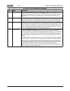
22 FRC8PIX Force 8-pixel Character Width. When VGA mode is enabled, setting this bit forces the
character width to be 8 pixels, overriding the setting in bit 0 (8-Dot character width) of the
VGA’s Sequencer Clocking Mode Register (index 01h). This causes the selection of an
8-pixel character width. This bit should be set for 640x480 flat panels when VGA fixed
timing mode is enabled.
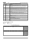
21 RSVD Reserved. Always set to 0.
20 YUVM YUV Mode. Selects YUV display mode for video overlay.
0: YUV 4:2:2 display mode.
1: YUV 4:2:0 display mode.
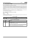
19 VDSE Video Downscale Enable.
0: Send all video lines to the display filter.
1: Use DC_VID_DS_DELTA (DC Memory Offset 080h[31:18]) as a Digital Differential
Analyzer (DDA) delta value to skip certain video lines to support downscaling in the
display filter.
18 VGAFT VGA Fixed Timing. When in VGA mode (VGAE bit 7 = 1), this bit indicates that the GLIU
block (DC) timing generator should provide the display timings. The VGA will slave its
display activity to the regular DC sync and display enable signals. The VGA image will be
centered on the screen, but not scaled to fill the screen. If upscaling is desired, the scaler
filter should be used instead of this feature. The final image must have at least six more
active lines than the native VGA display settings indicate (i.e., at least three lines of bor-
der on the top and bottom of the image).
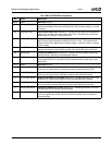
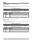
17 FDTY Frame Dirty Mode.
0: Frame buffer writes mark associated scan line dirty. Used when FB_PITCH (DC Mem-
ory Offset 034h[15:0]) is equal to 1 KB, 2 KB, or 4 KB.
1: Frame buffer writes mark entire frame as dirty. Used when FB_PITCH (DC Memory
Offset 034h[15:0]) is not equal to 1 KB, 2 KB, or 4 KB.
16 STFM Static Frame Mode. When compression is enabled (CMPE bit 5 = 1), this bit controls the
update of dirty scan lines.
0: Update dirty scan lines every frame.
1: Update dirty scan lines every other frame.
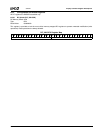
15:12 DFHPEL Display-FIFO High Priority End Level. This field specifies the depth of the display FIFO
(in multiples of 256 bytes) at which a high-priority request previously issued to the mem-
ory controller will end. The value is dependent upon display mode. This field should
always be non-zero and should be larger than the start level. Note that the settings in the
DC_ARB_CFG register (DC Memory Offset 00Ch) can also affect the priority of requests.
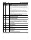
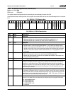
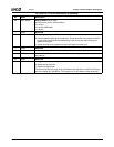
DC_GENERAL_CFG Bit Descriptions (Continued)
Bit Name Description


