AMD Geode™ LX Processors Data Book 249
Graphics Processor
33234H
6.3.7 8x8 Color Patterns
The new channel 3 hardware provides the capability of per-
forming BLTs with 64 pixel color patterns at all color
depths. To setup this mode, software first loads the pattern
data into the LUT beginning at address 100h The least sig-
nificant byte of this first DWORD contains the upper left
most pixel of the pattern. For 8-bpp mode, the most signifi-
cant byte of the next DWORD contains the upper right
most pixel of the pattern. In 16-bpp mode, the upper right
most pixel is contained in the most significant bytes of the
fourth DWORD, and for 32-bpp mode, the eighth DWORD
contains the upper right most pixel. The next line of the pat-
tern begins at the DWORD that follows the last pixel of the
previous line, such that the pattern is packed into the space
required to hold it. So for 8-bpp mode, the top left pixel is in
the least significant byte of the DWORD at address 100h in
the LUT, the top right pixel is in the most significant byte of
the DWORD at address 101. The bottom left pixel is in the
least significant byte of the DWORD at address 10Eh and
the bottom right pixel is in the most significant byte of the
DWORD at address 10Fh.
To enable this mode, the EN and PM bits should be set in
the GP_CH3_MODE_STR register (GP Memory Offset
64h[31, 21]): EN, PM. The PS, HS, RO, X, and Y bits
should not be set in the GP_CH3_MODE_STR register.
The BPP/FMT bits in the GP_CH3_MODE_STR register
(bits [27:24]) indicate the color depth of the pattern data. If
this does not match the BPP/FMT bits in the
GP_RASTER_MODE register (GP Memory Offset
38h[31:28]), then the pattern is translated to the depth
specified by the GP_RASTER_MODE register.
6.3.8 Source Data
When called for by the raster operation or alpha blender,
software should set the source required bits in the
GP_BLT_MODE register (GP Memory Offset 40h) so that
source data is fetched from the frame buffer memory or
can be written by the host to the GP_HST_SRC register
(GP Memory Offset 48h). Regardless of its origination,
source data can either be monochrome (expanded to two
colors) or color. The hardware aligns the incoming source
data to the appropriate pixel lanes for writing to the destina-
tion. Source data is only used when in BLT mode. In vector
mode, GP_SRC_COLOR_FG (GP Memory Offset 10h) is
forced onto the source channel.
6.3.8.1 Source Data Formats
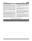
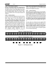
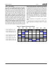
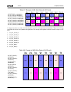
The Graphics Processor expects to see the left-most pixels
on the screen in the least significant bytes of the DWORD
and the right-most pixels in the most significant bytes. For
monochrome data within a byte, the left-most pixels are in
the most significant bits of the byte, and the right-most pix-
els are in the least significant bits. These formats are
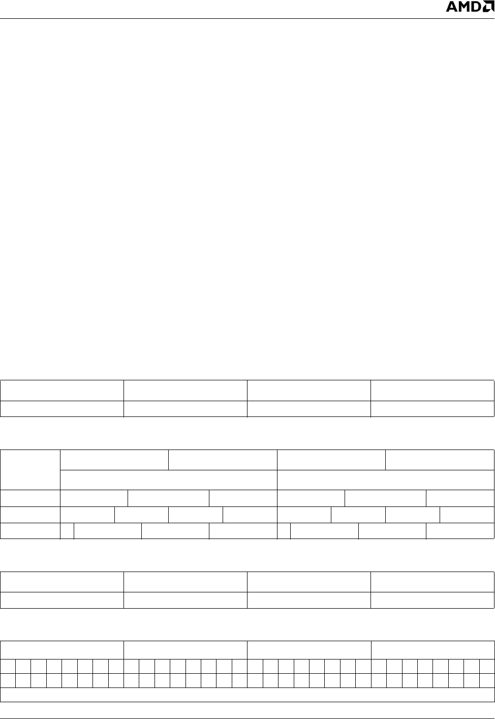
shown more clearly in Table 6-19, Table 6-20, Table 6-21,
and Table 6-22.
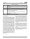
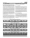
Table 6-19. 32-bpp 8:8:8:8 Color Data Format
Byte 3 Byte 2 Byte 1 Byte 0
Alpha/Unused Red Green Blue
Table 6-20. 16-bpp Color Data Format
Format
Byte 3 Byte 2 Byte 1 Byte 0
Right Pixel Data Left Pixel Data
5:6:5 Red Green Blue Red Green Blue
4:4:4:4 Alpha Red Green Blue Alpha Red Green Blue
1:5:5:5 A Red Green Blue A Red Green Blue
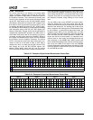
Table 6-21. 8-bpp 3:3:2 Color Data Format
Byte 3 Byte 2 Byte 1 Byte 0
Right Pixel Data (3:3:2) Pixel 2 Data Pixel 1 Data Left Pixel Data (3:3:2)
Table 6-22. Monochrome Data Format
Byte 3 Byte 2 Byte 1 Byte 0
01234567012345670123456701234567
24 25 26 27 28 29 30 31 16 17 18 19 20 21 22 23 8 9 10 11 12 13 14 15 0 1 2 3 4 5 6 7
Right Most Pixel Left Most Pixel


