AMD Geode™ LX Processors Data Book 565
GeodeLink™ Control Processor Register Descriptions
33234H
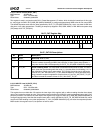
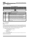
6.14.5.3 GLIU Device Interrupt Status (MSR_INTAX)
This is a read only MSR with the status of interrupt signals from the various blocks. This register is intended for debug pur-
poses. For functional interrupt handlers, the block-specific interrupt registers are memory-mapped. For devices that do not
support interrupts, the associated bit is 0.
MSR Address 4C000036h
Typ e RO
Reset Value 00000000_00000000h
MSR_INTAX Register Map
63 62 61 60 59 58 57 56 55 54 53 52 51 50 49 48 47 46 45 44 43 42 41 40 39 38 37 36 35 34 33 32
RSVD
31 30 29 28 27 26 25 24 23 22 21 20 19 18 17 16 15 14 13 12 11 10 9 8 7 6 5 4 3 2 1 0
RSVD
GLIU1_INT6
GLIU1_INT5
GLIU1_INT4
GLIU1_INT3
GLIU1_INT2
GLIU1_INT1
GLIU1_INT0
RSVD
RSVD
GLIU0_INT5
GLIU0_INT4
GLIU0_INT3
GLIU0_INT2
GLIU0_INT1
GLIU0_INT0
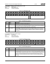
MSR_INTAX Bit Descriptions
Bit Name Description
63:15 RSVD Reserved.
14 GLIU1_INT6 Value of INTR signal from GLIU1, Port 6 (Security Block (AES)).
13 GLIU1_INT5 Value of INTR signal from GLIU1, Port 5 (VIP).
12 GLIU1_INT4 Value of INTR signal from GLIU1, Port 4 (GLPCI).
11 GLIU1_INT3 Value of INTR signal from GLIU1, Port 3 (GLCP).
10 GLIU1_INT2 Value of INTR signal from GLIU1, Port 2 (VP).
9 GLIU1_INT1 Value of INTR signal from GLIU1, Port 1 (GLIU).
8 GLIU1_INT0 Value of INTR signal from GLIU1, Port 0 (GLIU).
7 RSVD Reserved.
6 RSVD Reserved.
5 GLIU0_INT5 Value of INTR signal from GLIU0, Port 5 (GP).
4 GLIU0_INT4 Value of INTR signal from GLIU0, Port 4 (DC).
3 GLIU0_INT3 Value of INTR signal from GLIU0, Port 3 (CPU).
2 GLIU0_INT2 Value of INTR signal from GLIU0, Port 2 (GLIU)
1 GLIU0_INT1 Value of INTR signal from GLIU0, Port 1 (GLMC).
0 GLIU0_INT0 Value of INTR signal from GLIU0, Port 0 (GLIU).


