466 AMD Geode™ LX Processors Data Book
Video Input Port
33234H
6.9.5 Mode 1a,b,c - VIP Input Data
(simplified BT.656)
The VIP 2.0 specification describes an 8- or 16-bit data
stream incorporating both control and data. The data/con-
trol is delivered in packets. There are two different packet
types, SAV/EAV and ancillary packets. The specification
also requires backwards compatibility to VIP 1.1 data for-
mats. Three different VIP data modes are supported: VIP
1.1 compatible mode, VIP 2.0 8-bit mode, and VIP 2.0 16-
bit mode. Differences in these modes are noted in the
descriptions of the different packet types in Section 6.9.5.1
on page 466.
6.9.5.1 SAV/EAV Packets
The SAV/EAV packets begin with 3 bytes of preamble fol-
lowed by a Start of Active Video (SAV) status WORD.
Active data follows. The packet ends with the reception of
another 3 bytes of preamble followed by an End of Active
Video (EAV) status WORD. The preamble consists of FF-
00-00. The codes FF and 00 codes are prohibited as video
samples and reserved for header and synchronization pur-
poses. The code 00 can be used within a packet to mark an
empty cycle. If a 00 code appears between the SAV and
EAV, that sample is ignore. Note that in 16-bit mode, only
the 8 LSBs are checked. If 00, the entire 16-bit WORD is
ignored. The preamble and status WORD always occurs on
bits [7:0] of the input data, even in 16-bit mode. The active
data is received on bits [7:0] in 8-bit mode and on bits
[15:0] in 16-bit mode. The Y values appear on bits [7:0] and
Cx values on bits [15:8]. Both active video and VBI data are
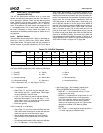
received in SAV/EAV packets. The format of the SAV and
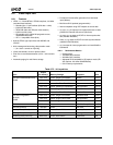
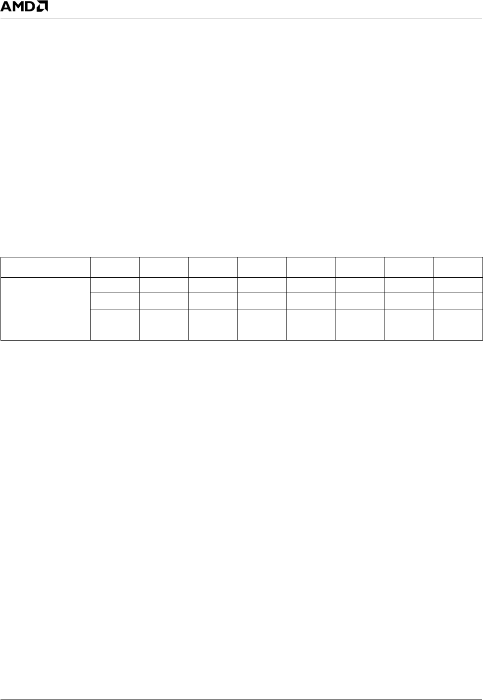
EAV preamble and status WORD is shown in Table 6-73. A
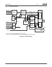
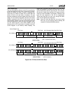
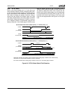
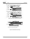
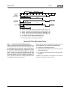
sample SAV/EAV line is shown in Figure 6-40 on page 467.
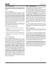
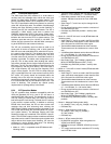
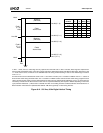
A full frame is shown in Figure 6-41 on page 468.
The status WORD provides the raster reference information:
VIP 1.1 compatible mode:
— Video Flags T, F, and V can only be changed in the
EAV code per the VIP 1.1 specification. These flags
are only captured in the EAV code.
— In VIP 1.1, the Task bit is used to indicate VBI data
within the video stream (T = 0 for VBI data, T = 1 for
active video). In VIP 1.1 mode, the Task bit is used in
place of the V bit to indicate VBI data.
— P3-P0 are ignored.
VIP 2.0 modes (8- or 16-bit data):
— Video Flags T, F, and V are valid in the EAV and SAV
code. Valid values must appear no later then the SAV
of the first scan line of the next active region.
— Task bit differentiates between two video streams.
These streams can be interleaved at a line or field
rate.
— V bit differentiates between active video and VBI data
(V = 1 for VBI data, V = 0 for active video).
— New Video Flags - The P Nibble is redefined as
[NON_INT,REPEAT,Reserved,EXT_FLAG]:
– NON_INT: 1 = non-interlaced source, 0 = inter-
laced source (not used).
– REPEAT: 1 = Repeat field in 3:2 pull-down, 0 = not
a repeat field (repeat fields can be ignored by
VIP). The repeat flag must be set in the SAV for
every line in the field. The line will be saved to
memory if the repeat flag is not set. (This function
needs to be enabled in VIP Memory Offset
04h[29]).
– EXT_FLAG: 1 = Extra flag byte follows this EAV, 0
= no extra flag byte (not implemented).
Table 6-73. SAV/EAV Sequence
Parameter D7D6D5D4D3D2D1D0
Preamble 11111111
00000000
00000000
Status WORD T F V H P3 P2 P1 P0
T = Task BIT 0 = Task B 1 = Task A
F = Field ID 0 = Odd 1 = Even
V = Vertical blanking 0 = Active video 1 = Vertical blanking
H = Horizontal blanking 0 = Active line 1 = Horizontal blanking
P3-0 = Reserved in VIP 1.1, New Flags in VIP 2.0


