


EPSON Stylus Pro 7600/9600 Revision A
Operating Principles Print Mechanism Components 102
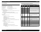
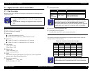
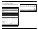
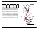
2.2 Print Mechanism Components
The major electrical parts used in the printer mechanism of this printer are as shown
below. Hereafter, we will explain each printer mechanism focusing on these parts.
Table 2-1. Printer Mechanism Components
Part
Drive
voltage
Description
Refer
to
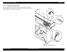
Carriage (CR) Mechanism (p.103)
Print head
The number of nozzles: 96
Nozzle x 7 colors
p.105
Head thermistor +3.3V Incorporated in the print head
CR motor +42V DC motor p.104
CR_HP sensor
(Carriage origin)
+3.3V Transmission type photo-interrupter
p.104
CR encoder sensor +5V Linear encoder (180LPI) p.104
Pump motor +42V DC motor p.115
HD_SLID sensor
(Head slide origin)
+3.3V Reflection type photo-interrupter p.107
P_EDGE sensor
(Paper edge)
+5V Reflection type photo-interrupter
p.108
Cutter solenoid +24V DC solenoid p.112
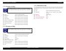
Paper Feed Assembly (p.113)
PF motor +42V DC motor p.113
PF encoder sensor +5V Linear encoder (360LPI) p.113
Paper suction fans +24V
The number of DC blowers
Stylus Pro 7600: 2
Stylus Pro 9600: 3
p.114
P_REAR sensor
(Paper rear)
+5V Reflection type photo-interrupter
p.114
P_THICK_0.3 sensor
(Paper thickness)
+3.3V/
+5V
Transmission type photo-interrupter p.114
P_THICK sensor
(Paper thickness)
+5V Transmission type photo-interrupter
p.114
Release Sensor
(I/H lever)
+5V Limit switch p.114
Ink Supply Mechanism (p.117)
Pump motor +42V DC motor p.115
Cleaning Mechanism (p.115)
Ink ID
+5V,
+3.3V
CSIC p.117
Maintenance tank
+5V,
+3.3V
CSIC p.115
Others (p.118)
Cover open sensor
(Cover Open L)
+3.3V Limit switch
p.118
MAIN board Printer control/drive circuit board p.119
Radiator cooling fan +5V DC brushless fan
Dip swich – Dip swich
p.207
Jumper – Jumper
Power supply board – p.120
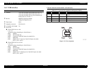
Table 2-1. Printer Mechanism Components (continued)
Part
Drive
voltage
Description
Refer
to