


EPSON Stylus Pro 7600/9600 Revision A
Disassembly & Assembly Disassembly and Assembly of Carriage (CR) Mechanism 180
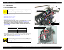
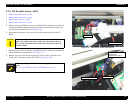
4.3.7 CR Motor ASSY
This section describes the replacement procedure for the following parts of the CR
Motor ASSY.
CR Timing Belt
Driven Pulley
(Stylus Pro 7600: white / Stylus Pro 9600: black)
1.
Remove the R Side Cover. (p.160)
2.
Remove the L Side Cover. (p.163)
3.
Remove the I/H Cover. (p.164)
4.
Remove the H Top Cover. (p.165)
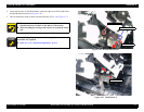
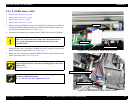
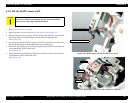
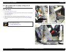
5. Release the carriage lock and move the carriage from the capping position.
(See Figure 4-24)
6. On the R Side Frame side, remove the CR Tension Mounting Shaft and CR Tension
Spring and the CR Tension Spring Support.
(See Figure 4-42)
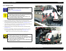
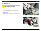
7. Slide the CR Tension Bracket to the left (toward the CR Motor), and remove the CR
Timing Belt, together with the Driven Pulley, from the CR Tension Bracket.
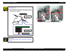
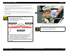
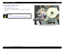
Figure 4-41. Indicator Position
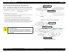
Figure 4-42. Loosening the CR Timing Belt
Before installing the covers, adjust the indicator position (the right
end of the projection on the CR tension spring support) of the CR
tension bracket to the center by turning the CR Tension Mounting
Shaft.
However, if the indicator was at a off-center position before
assembly, adjust the indicator to the same off-center position. (See
Figure 4-42)
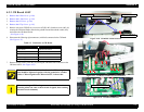
Adjust the right end to the center
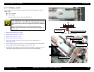
Projection (CR tension
spring support)
Remove the CR Tension
Mounting Shaft
Driven Pulley
CR Tension Bracket
Timing Belt
CR Tension Spring
CR Tension Spring Support
Record scale reading