


EPSON Stylus Pro 7600/9600 Revision A
Operating Principles Print Mechanism Components 104
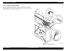
CARRIAGE MOVING UNIT
In place of the carriage holding system in which 2 CR guide shafts extending in the
column direction were used, as in the conventional models, a structure with the
carriage mounted via multiple rollers (bearings) on a CR guide rail made of a square
extruded aluminum pipe is used. Steel rails are incorporated in the roller contact and
running surface, and the result is a reduction in friction in the direction of movement,
reduced vibration and improved durability.
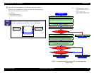
CR motor
A DC motor is used for the CR motor and the slit in the timing fence affixed on the
bottom of and parallel with the CR guide rail is read by the encoder sensor
mounted on the carriage (linear encoder system), and this signal is compared to
logical control values in the control circuit on the MAIN board, which carries out
feedback speed control. Through this control, high print precision is maintained.
Drive transmissions from the CR motor to the carriage use the easy-to-maintain,
durable timing belt.
The sensors used in the carriage moving unit are described below.
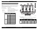
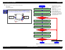
CR_HP Sensor (Carriage Home Position)
This is a transmissive photosensor which is mounted on the right end of the printer
mechanism and detects the entry position of the flag (projection) provided on the
carriage as the carriage moving home position. Outputs from this sensor are
“OFF” in the HP range and “ON” outside the HP range.
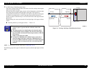
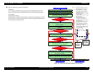
CR encoder sensor (Linear Encoder)
This encoder is mounted on the back of the carriage and outputs pulses (2
channels) corresponding to the position of the slit on the timing fence that is
incorporated into the CR guide rail which are used for CR motor servo control and
PTS (Print Timing Signal) generation. The resolution is 1/180 inch.
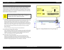
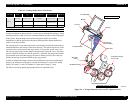
Figure 2-2. Carriage Mechanism Unit, Carriage Moving Unit
C A U T I O N
The screws used to fasten the CR guide rail should not be taken out
and the carriage should not be removed. These are adjusted and
assembled to the nearest 1/100 mm at the factory.
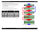
Projection on Carriage
CR_HP Sensor
Outside HP range Inside HP Range
Step Ruler (Slit Plate)
CR_HP Sensor
(Mounted on the
mechanism’s right
end.)
Encoder Sensor
(On Carriage)
CR Motor
CR Timing Belt
Encoder Sensor
Carriage
HP Flag