


EPSON Stylus Pro 7600/9600 Revision A
Disassembly & Assembly Disassembly and Assembly of Carriage (CR) Mechanism 181
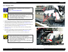
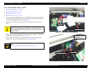
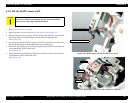
8. Loosen the CR Tension Mounting Shaft on the R Side Frame side, then release the
tension on the CR Timing Belt.
(See Figure 4-43)
9. Disconnect the connector of the CR Motor harness and the relay connector from the
Main Board, unclamp the CR Motor harness and take them out through the hole in the
Left Side Frame.
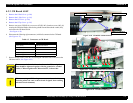
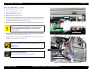
10. Remove the timing belt from the CR Motor ASSY pulley on the L Side Frame.
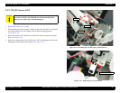
11. Take out the four screws (CP(W): M4
×
10) holding the CR Motor ASSY, then remove
the CR Motor ASSY.
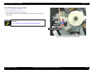
Figure 4-43. Removing the CR Motor ASSY
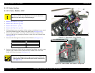
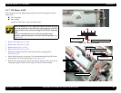
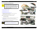
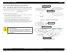
Remember that there is a difference in specifications between
the driven pulley (white) of Stylus Pro 7600 and the driven
pulley (black) of Stylus Pro 9600.
Set the timing belt of Stylus Pro 7600 on the CR Unit in a
manner as shown below:
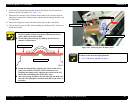
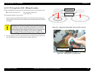
Install the timing belt by adjusting the tension on the driven
pulley side, with the CR Motor secured with the screws.
Installing the timing belt by adjusting the tension on the CR
Motor side could damage the PF Encoder Scale.
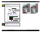
Move the carriage by hand to the left and right and make sure
that the CR Timing Belt is attached uniformly in the center of
the pulley.
CR Unit
Flat surface hereCR Timing Belt
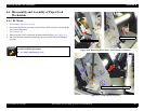
A D J U S T M E N T
R E Q U I R E D
Once the belt tension has changed as a result of, say, removal of the
CR Motor, make the following adjustment:
“5.1.4.3 CR Motor Adjustment” (p.214)
Screws (CP(W): M4×10) ×4
CR Motor ASSY
Connector
CR Timing Belt