


EPSON Stylus Pro 7600/9600 Revision A
Adjustment Mechanism Adjustment 269
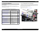
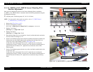
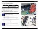
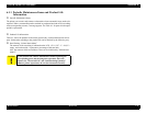
5.3.7 Cutter Positioning Adjustment
This adjustment should definitely be mad if the following parts are removed.
This adjustment is intended to install the cutter at a proper position and height relative
to the step for the cutter on the Paper Guide L. The number of adjustment items
required depends on the parts replaced. Carry out work by referring to the table above.
Adjusting tools: Cutter positioning jig #F800
NOTE: For disassembly and assembly procedure, refer to “Cutter Holder ASSY
(p.175)”.
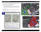
1. Remove the
H Top Cover. (p.165)
NOTE:
For Stylus Pro 9600, remove also the
H Top Cover (p.165)
and the
Tube Cover
(p.193)
.
2. Open the Front Cover, and remove the cutter.
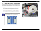
3. Return the CR Unit to the cap position and set the cutter positioning tool at the right
end of the Paper Guide L.
(See Figure 5-73)
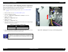
4. Loosen the screws securing the Paper Guide L.
NOTE:
3 screws for Stylus Pro 7600 / 5 screws for Stylus Pro 9600
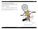
Figure 5-71. Cutter Positioning Adjustment
Figure 5-72. Removing the screw for Paper Guide L (at left end)
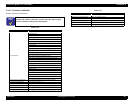
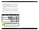
Parts Adjustment Items
Cutter Solenoid Assy 1. Paper Guide L up and down adjustment
2. Cutter Holder ASSY height adjustment
Paper Guide L 1. Paper Guide L up and down adjustment
C H E C K
P O I N T
For adjustments at replacing the Cover Sensor ASSY, make the
Paper Guide L up and down adjustment first and then make the
Cutter Holder ASSY height adjustment.
C H E C K
P O I N T
To loosen the screw at the left end of the Paper Guide L, pass the
screwdriver through the cut portion of the I/H Frame Top Plate.
(See Figure 5-72)
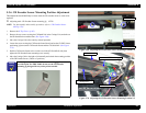
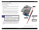
Paper Guide L up and down adjustment
Cutter Holder ASSY height adjustment
Cut portion of I/H Frame