


EPSON Stylus Pro 7600/9600 Revision A
Disassembly & Assembly Disassembly and Assembly of Carriage (CR) Mechanism 174
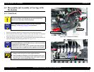
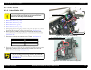
4.3.3 CR Board ASSY
1.
Remove the R Side Cover. (p.160)
2.
Remove the L Side Cover. (p.163)
3.
Remove the I/H Cover. (p.164)
4.
Remove the H Top Cover. (p.165)
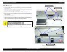
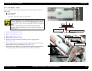
5. Remove one screw (CPP M3
×
6), two screws (CP(W): M3
×
6) and one screw (M3
×
16)
securing the CR Board Guide, and also the ground line and the toothed washer (M3),
and remove the CR Board Guide.
(See Figure 4-30)
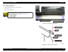
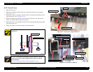
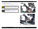
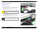
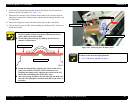
6. Disconnect the following eight connectors (with lock) connected to the CR Board.
(See Figure 4-31)
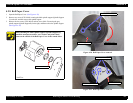
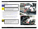
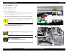
7. Remove the two screws (CPP: M3
×
8) securing the CR Board ASSY and remove the
CR Board ASSY.
(See Figure 4-32)
Figure 4-30. CR Board Guide Removal
Figure 4-31. CR Board Connectors Disconnection
Figure 4-32. CR Board Removal
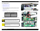
Table 4-3. Connectors on CR Board
Connector Type Connected to
5-Pin (white) CR Encoder Sensor
4-Pin (black) P_EDGE Sensor
2-Pin (white) Cutter Solenoid
FFC (lock type)×2 Print Head
FFC (lock type)×3 Main Board
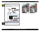
The screw on the far left side used to fasten the CR board guide
plate should be tightened together with the ground wire, toothed
washer, CR board guide and CR board ASSY, in that order.
C A U T I O N
When connecting an FFC, take great care not to insert it aslant.
(Inserting aslant can cause a short circuit of signals, thus resulting
in broken circuit elements.)
CR Board Guide Plate
Screw (CPP: M3×6)
Screws (CP(W): M3×6) ×2
Screws (M3×16)
Screws (CPP: M3×8) ×2