


EPSON Stylus Pro 7600/9600 Revision A
Disassembly & Assembly Disassembly and Assembly of Circuit Boards 207
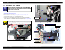
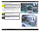
4.7.3 MAIN Board (C472 MAIN)
1.
Remove the Rear Cover. (p.166)
2. Disconnect all the harness connectors from the Main Board.
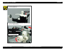
3. Remove the two screws (CP(W): M3
×
6) securing the both ends of the parallel interface
connector to the Main Board and seven other screws (CP(W): M3
×
6), and remove
Main Board.
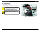
Figure 4-83. C472MAIN Board Removal
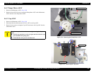
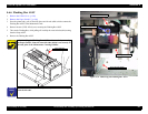
Figure 4-84. Harness Clamp Locations
C A U T I O N
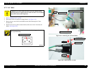
When disconnecting or connecting the connector for an FFC cable
on the Main Board, never pull or push the connector aslant.
Disconnecting or connecting the connector can cause damage to,
short circuit or breakage of the terminals inside the connector, thus
resulting in damage to elements on the circuit board.
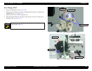
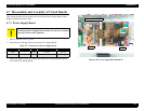
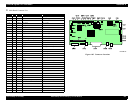
Refer to the table on the next page for connections of connectors.
The following connectors are not used:
CN4, CN7, CN12, CN18, CN25, CN28, CN33, CN36, CN37
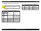
A D J U S T M E N T
R E Q U I R E D
Before and after replacing the Main Board with a new one, make
the following adjustment:
Refer to “5.1.4.2 Main Board Adjustment” (p.213)
Screws (CP(W): M3×6) × 9