


EPSON Stylus Pro 7600/9600 Revision A
Disassembly & Assembly Summary 157
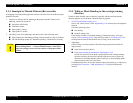
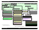
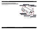
Figure 4-2. Disassembly Process Flowchart
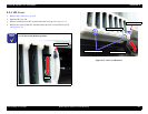
4.3.1 Print Head (p.171)
4.3.2 Damper ASSY (p.173)
4.3.3 CR Board ASSY (p.174)
4.3.4 Cutter Section (p.175)
4.3.4.1 Cutter Holder ASSY (p.175)
4.3.4.2 Cutter Solenoid (p.177)
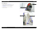
4.3 Disassembly and Assembly of Carriage (CR) Mechanism (p.171)
4.3.7 CR Motor ASSY (p.180)
4.4 Disassembly and Assembly of Paper Feed Mechanism (p.185)
4.3.8 HEAD_SLIDE Sensor ASSY (p.182)
4.3.9 CR_HP Sensor ASSY
(p.183)
4.3.10 CR Encoder Scale (Timing Fence)
(p.184)
4.5 Disassembly and Assembly of Ink Supply Mechanism (p.192)
4.6 Disassembly and Assembly of Cleaning Mechanism (p.198)
4.7 Disassembly and Assembly of Circuit Boards (p.205)
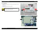
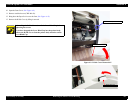
4.2 Removing the Panel Unit and Housing (p.158)
4.7.3 MAIN Board (C472 MAIN) (p.207)
4.7.2 AC Inlet (p.206)
4.7.1 Power Supply Board (p.205)
4.6.1 Maintenance ASSY Removal (p.199)
4.6.2 Pump Motor ASSY (p.200)
4.6.3 Cap ASSY (p.200)
4.6.4 Pump ASSY (p.201)
4.6.5 Cleaner Head (Wiper) (p.203)
4.4.1 PF Motor (p.185)
4.4.4 Suction Fans (p.189)
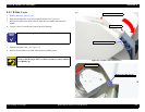
4.2.2 R Side Cover (p.160)4.2.3 L Side Cover (p.163)
4.2.6 Rear Cover (p.166)
4.2.4 I/H Cover (p.164)
4.2.1 Panel Unit (p.159)
4.2.5 H Top Cover (p.165)
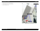
4.2.7 Paper Guide L2 (p.168)
4.2.8 Roll Paper Cover (p.169) 4.2.9 Front Cover (p.170)
4.5.1 C472_SUB-B Board (p.192)
4.5.3 Cover Sensor ASSY (p.197)
4.4.6 P_REAR Sensor ASSY (p.191)
4.4.5 P_THICK Sensor/P_THICK Sensor_0.3
ASSY (p.190)
4.5.2 I/H (Ink Holder) ASSY (p.193)
Release Sensor (I/H Lever) (p.193)
CSIC Relay Board (p.193)
4.3.5 CR Encoder Sensor ASSY (p.178)
4.3.6 P_EGDE Sensor ASSY (p.179)
4.4.2 PF Encoder Sensor ASSY (p.186)
4.4.3 Cautions when replacing the PF Loop Scale (p.187)
4.6.6 Flushing Box ASSY (p204)
Note: The italic bold characters represent
consumables or regular replacement parts.