


EPSON Stylus Pro 7600/9600 Revision A
Disassembly & Assembly Disassembly and Assembly of Ink Supply Mechanism 193
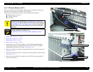
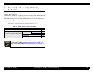
4.5.2 I/H (Ink Holder) ASSY
There are a total of seven I/H assemblies installed, one for each ink color. Here, the
procedure for removing one I/H ASSY will be explained.
This section also describes the procedure for removing the following parts:
Release Sensor (I/H Lever)
CSIC Relay Board
I/H Frame
1.
Remove the R Side Cover. (p.160)
2.
Remove the L Side Cover. (p.163)
3.
Remove the I/H Cover. (p.164)
4.
Remove the H Top Cover. (p.165)
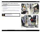
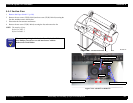
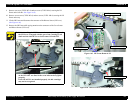
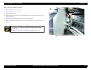
5. Disconnect the seven FFCs (ink cartridges), two FFCs (Main Board/Maintenance
Tank) and the connector for the Release Sensor (I/H Lever) on the C472_SUB-B
Board found at the left side of I/H Frame.
(See Figure 4-62)
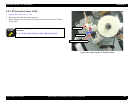
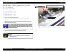
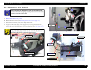
6. Remove two black screws (M3
×
8) securing the Ink Tube Cover and remove the cover
.
(See Figure 4-63)
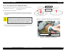
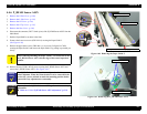
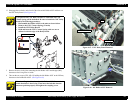
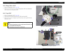
7. Disconnect the connector of the Cover Sensor ASSY at the right side of the I/H Frame.
(See Figure 4-64)
8. Remove one screw (CUPS: M3
×
6) and one screw (CUPS: M4
×
6) securing the I/H
Frame on the right side.
Figure 4-63. Ink Tube Cover Removal
Figure 4-64. I/H Frame Removal 1/2
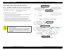
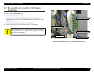
C A U T I O N
You must execute ink discharge (
“Ink Blowing”
in
5.2.3.20 Clean
Head on page 256
) before removal of the I/H ASSY and ink charging
(
“Initial charge”
in
5.2.4 Cleaning on page 259
) after reinstallation.
If no ink tube is to be removed, there is no need of executing ink
discharge.
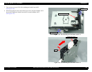
A D J U S T M E N T
R E Q U I R E D
When removing and installing the front cover switch holder, the
following adjustment should be made.
Refer to “5.1.4.9 Cover Sensor ASSY Adjustment” (p.216)
Black screws (M3×8) ×2
Tube Cover
Connector of Cover Sensor ASSY
Screw (CUPS: M3×6)
Screw (CUPS: M4×6)