


EPSON Stylus Pro 7600/9600 Revision A
Disassembly & Assembly Disassembly and Assembly of Paper Feed Mechanism 191
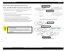
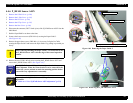
4.4.6 P_REAR Sensor ASSY
1.
Remove the R Side Cover. (p.160)
2.
Remove the L Side Cover. (p.163)
3.
Remove the I/H Cover. (p.164)
4.
Remove the H Top Cover. (p.165)
5.
Remove the Rear Cover. (p.166)
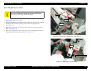
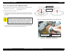
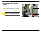
6. Disconnect the connector (CN27: black 4-pin) of the P_REAR Sensor ASSY from the
Main Board.
7. Push the Paper Hold Lever down to the front.
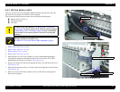
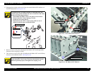
8. Remove the lower two screws (CBS: M4
×
6) securing the Paper Guide U.
(See Figure 4-60)
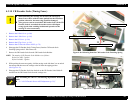
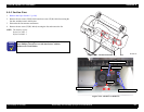
9. Remove the upper three screws (CBS: M4
×
6) (six screws for Stylus Pro 7600)
securing the Paper Guide U and remove the Paper Guide U by pulling it up toward you
slowly.
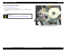
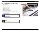
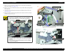
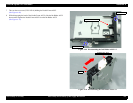
10. Remove the two (CP(W): M2
×
8) screws securing the P_REAR Sensor ASSY and
remove the P_REAR Sensor ASSY.
(See Figure 4-61)
Figure 4-60. Removing the Paper Guide U
Figure 4-61. Removing the P_REAR Sensor ASSY
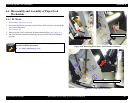
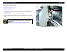
C A U T I O N
When removing/installing the Paper Guide U, be careful not to mar
the P_REAR Sensor ASSY with the edge of the sensor inspection
window.
C H E C K
P O I N T
The P_REAR Sensor ASSY position is adjusted at the factory
before shipment. When the sensor bracket is to be removed on the
service site, you are advised to mark the mounting position before
removal for easy adjustment at reassembly.
A D J U S T M E N T
R E Q U I R E D
If you replace the P_REAR Sensor ASSY, perform the necessary
adjustment.
Refer to “5.1.4.6 P_REAR Sensor ASSY Adjustment” (p.215)
Paper Guide U
P_REAR Sensor ASSY peeping window
Screws (M4×6) ×5
P-REAR Sensor ASSY
Screws (M2×8) ×2