


EPSON Stylus Pro 7600/9600 Revision A
Disassembly & Assembly Removing the Panel Unit and Housing 166
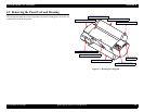
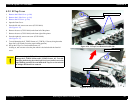
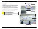
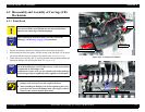
4.2.6 Rear Cover
1. From the rear side, remove two screws (CPS: M3
×
12), and remove the blank panel.
(See Figure 4-16)
2. Remove the two screws (CP: M3
×
6) securing the parallel interface and remove the one
screw (CBS: M3
×
6) securing the USB interface.
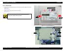
3. Remove one screw (CBS: M3
×
6) holding the AC inlet top.
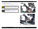
(See Figure 4-17)
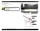
4. Remove the three screws (CBS: M4
×
8) (six screws for Stylus Pro 9600) holding the
rear cover bottom.
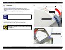
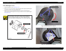
5. Open the Roll Paper Cover.
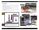
6. Remove the three screws (CBS: M4
×
8) (six screws for Stylus Pro 9600) holding the
rear cover top, then remove the rear cover, while pulling it rearward.
Figure 4-16. Rear Cover Removal 1/2
Figure 4-17. Rear Cover Removal 2/2
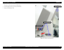
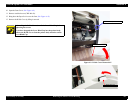
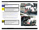
C A U T I O N
To avoid getting hurt with sharp frame edges, be sure to wear
gloves when performing the following work:
Removing and installing the Rear Cover
Inserting your hand through the opening in the Access Cover
(see Check Point on the next page)
Screws (CPS: M3×12) ×2
Blank Panel
Screw (CPS: M3×6)
Screws (CPS: M3×6) ×2
Screw (CPS: M3×6)
Screws (CPS: M4×8) ×3
Screws (CPS: M4×8) ×3