


EPSON Stylus Pro 7600/9600 Revision A
Adjustment Mechanism Adjustment 268
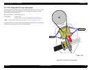
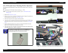
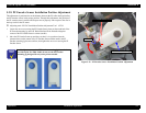
5.3.6 CR Encoder Sensor Mounting Position Adjustment
This adjustment should definitely be done when the CR encoder sensor is removed or
replaced.
Adjusting tools: CR Encoder Sensor mounting jig #F799
NOTE: For disassembly and assembly procedure, refer to “CR Encoder Sensor
ASSY (p.178)”.
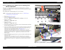
1. Remove the
H Top Cover. (p.165)
2. Remove the two screws securing the CR Board Unit in the Carriage Unit, and take out
the CR Board Unit toward the front.
(See Figure 5-69)
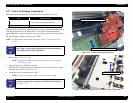
3. Move the Carriage Unit to the center by manual operation.
4. Loosen the screw securing the CR Encoder Sensor Board, and set the CR ENC Sensor
positioning jig between the CR Encoder Sensor and the CR Guide Rail.
(See Figure
5-70)
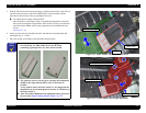
5. Push the CR Encoder Sensor to the exclusive tool side (CR Guide Rail side), then
tighten the CR Encoder Sensor mounting screw securely.
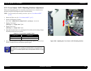
6. Move the Carriage Unit to the right or left manually and recheck the mounting position
of the CR Encoder Sensor. (Check at 3 positions)
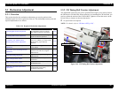
Figure 5-69. Adjusting the CR Encoder Sensor Mounting Position 1/2
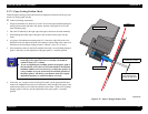
Figure 5-70. Adjusting the CR Encoder Sensor Mounting Position 2/2
C H E C K
P O I N T
In this adjustment, use the CR Encoder mounting jig for exclusive
use with Stylus Pro 7600 / 9600: do not use the CR Encoder
mounting jig designed for any other printer models.
2 screws
CR Board Unit
CR Encoder Sensor
CR Encoder Scale
(Timing Fence)
CR Guide Rail
CR Encoder Sensor mounting jig