


EPSON Stylus Pro 7600/9600 Revision A
Adjustment Mechanism Adjustment 272
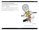
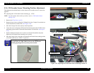
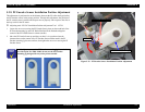
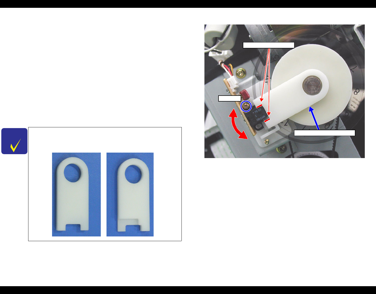
5.3.8 PF Encoder Sensor Installation Position Adjustment
This adjustment is performed to set the distance between the PF roller shaft (grid roller)
and PF encoder sensor in the proper position. Through this adjustment, the position of
the PF encoder sensor's emitter and receptor are set properly with respect to the slits in
the loop scale for the PF motor.
Adjusting tools: PF ENC Installation Position Adjustment Tool #F798
1. Loosen the one screw securing the PF Encoder Sensor, then put the round hole of the
PF Encoder mounting jig on the PF Roller Shaft and fit the notched end against
contour of the PF Encoder Sensor's emitter (outside).
2. Move the PF Encoder Sensor up and down so that it is in a position where the
clearance between the contour of the PF Encoder Sensor and the notch in the PF
Encoder mounting jig becomes uniform, then tighten the one screw securing the PF
Encoder Sensor.
Figure 5-76. PF Encoder Sensor Installation Position Adjustment
C H E C K
P O I N T
In this adjustment, use the PF Encoder mounting jig for exclusive
use with Stylus Pro 7600 / 9600: do not use the PF Encoder
mounting jig designed for any other printer models.
PF Encoder Sensor mounting jig
Screw
Check the clearance here