


EPSON Stylus Pro 7600/9600 Revision A
Disassembly & Assembly Disassembly and Assembly of Carriage (CR) Mechanism 178
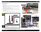
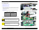
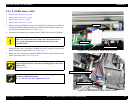
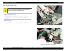
4.3.5 CR Encoder Sensor ASSY
1.
Remove the R Side Cover. (p.160)
2.
Remove the L Side Cover. (p.163)
3.
Remove the I/H Cover. (p.164)
4.
Remove the H Top Cover. (p.165)
5.
Remove one screw (CPP M3
×
6), two screws (CP(W): M3
×
6) and one screw (M3
×
16)
securing the CR Board Guide, and also the ground line and the toothed washer (M3),
and remove the CR Board Guide.
(See Figure 4-30)
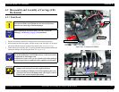
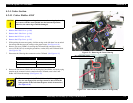
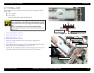
6. Disconnect the connector (5-pin, white) for the CR Encoder Sensor from the CR
Board.
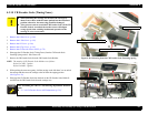
7. Remove the two screws securing the CR Board Unit in the Carriage Unit, and take out
the CR Board Unit toward the front.
(See Figure 4-37)
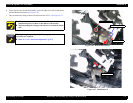
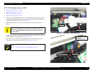
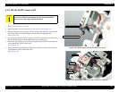
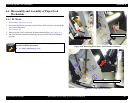
8. Remove one screw (CPP: M3
×
8) securing the CR_ENC ASSY, ground line, and
washer (M3). Then remove the CR_ENC ASSY.
(See Figure 4-38)
Figure 4-37. CR Encoder Sensor Removal 1/2
Figure 4-38. CR Encoder Sensor Removal 2/2
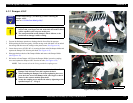
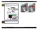
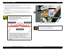
C A U T I O N
If you can not disconnect easily the connector for the CR Encoder
Sensor, do not disconnect it by undue force. Disconnect the two
FFCs for the print head first and then the connector for the CR
Encoder Sensor.
A D J U S T M E N T
R E Q U I R E D
After assembling the CR ENC, the following adjustments should be
made.
“5.1.4.8 CR Encoder Sensor ASSY Adjustment (p.215)”
CR Board Unit
Connector
CR_ENC ASSY
Ground line
Screw (M3×8)
Ground line
Toothed washer (M3)