


EPSON Stylus Pro 7600/9600 Revision A
Disassembly & Assembly Disassembly and Assembly of Carriage (CR) Mechanism 182
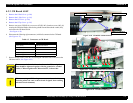
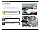
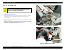
4.3.8 HEAD_SLIDE Sensor ASSY
1.
Remove the R Side Cover. (p.160)
2. Remove the Access Cover. (See
Removing the Access Cover on page 167)
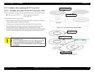
3. While pushing the cutter area gently, shift the carriage to the left about 2 cm to unlock
the carriage and then move the carriage to the left from the capping position.
(See Figure 4-24)
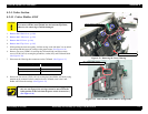
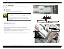
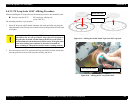
4. Disconnect the connector (CN29: red 4-pin) of the HEAD_SLIDE Sensor ASSY from
the Main Board and take it out through the hole in the R Side Frame.
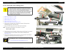
5. Remove the one (CP(W): M3
×
6) screw securing the HEAD_SLIDE Sensor ASSY and
remove the HEAD_SLIDE Sensor ASSY.
(See Figure 4-44)
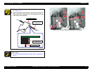
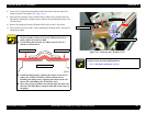
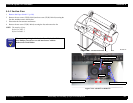
6. Release the harness for the HEAD_SLIDE Sensor ASSY from the five cable clamps on
the Maintenance ASSY and CR Rail ASSY.
(See Figure 4-45)
Figure 4-44. Removing the HEAD_SLIDE Sensor ASSY
Figure 4-45. Releasing the HEAD_SLIDE Sensor ASSY Harness
C A U T I O N
When unlocking the carriage, do not move the carriage by about 2
cm or more with the cutter pushed into the innermost position;
otherwise, the cutter edge would be damaged.
Screws (CP(W): M3×6)
HEAD_SLIDE Sensor ASSY
Clamp
Clamp
Clamp
Clamp