


EPSON Stylus Pro 7600/9600 Revision A
Product Description Interfaces 93
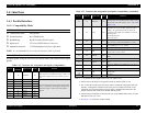
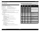
1.6.1.2 Nibble Mode
SPECIFICATION
Transmission mode: 8 bit parallel
Synchronization: By STROBE pulse
Handshaking: By BUSY and ACKNLG signal
Signal level: TTL compatible (IEEE1284Level 1 device)
Data trans. timing: Refer to the IEEE-1284 specification
Extensibility Request:
The printer responds affirmatively when the extensibility request values are 00H
or 04H, that mean,
00H Request Nibble Mode Reverse Channel Transfer.
04H Request Device ID; Return Data Using Nibble Mode Rev Channel
Transfer.
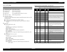
Device ID:
When IEEE1284.4 is valid
• <xx><xx>
(Character strings, depending on <Model Name>)
• MFG: EPSON;
• CMD: ESCPL2,BDC,D4;
• MDL: <Stylus Pro 7600-DYE/Stylus Pro 9600-DYE>;
• CLS: PRINTER;
• DES: EPSON<SP><Stylus Pro 7600-DYE/Stylus Pro 9600-
DYE>;(<SP>:space)
When IEEE1284.4 is not valid
• <xx><xx>
(Character strings, depending on <Model Name>)
• MFG: EPSON;
• CMD: ESCPL2,BDC;
• MDL: <Stylus Pro 7600-DYE/Stylus Pro 9600-DYE>;
• CLS: PRINTER;
• DES: EPSON<SP>T<Stylus Pro 7600-DYE/Stylus Pro 9600-DYE>;
(<SP>:space)
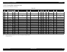
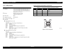
CONNECTOR PIN ASSIGNMENT AND SIGNALS
Note "*": In/Out refers to the direction of signal flow from the printer's point of view.
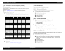
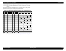
Table 1-55. Connector Pin Assignment and Signals (Nibble)
Pin
No.
Return
GND Pin
Signal Name In/Out * Function
1 19 HostClk In Host clock signal.
2 20 DATA0 In
The DATA0 through DATA7 signals
represent data bits 0 to 7, respectively. Each
signal is at high level when data is logical 1
and low level when data is logical 0.
3 21 DATA1 In
4 22 DATA2 In
5 23 DATA3 In
6 24 DATA4 In
7 25 DATA5 In
8 26 DATA6 In
9 27 DATA7 In
10 28 PtrClk Out Printer clock signal.
11 29
PtrBusy
/DataBit-3,7
Out
Printer busy signal and reverse channel
transfer data bit 3 or 7.
12 28
AckDataReq
/DataBit-2,6
Out
Acknowledge data request signal and reverse
channel transfer data bit 2 or 6.
13 28
Xflag
/DataBit-1,5
Out
X-flag signal and reverse channel transfer
data bit 1 or 5.
14 30 HostBusy In Host busy signal.
31 30 -INIT In Not used.
32 29
-DataAvail
/DataBit-0,4
Out
Data available signal and reverse channel
transfer data bit 0 or 4.
36 30 1284-Active In 1284 active signal.
18 -- Logic H Out
Always “HIGH”. Pulled up to +5 V via 3.9 K
ohm resistor.
35 -- +5V Out
Always “HIGH”. Pulled up to +5 V via 1.0 K
ohm resistor.
17 -- Chassis GND -- Chassis GND.
16,33,
19-30
-- GND -- Signal GND.
15,34 -- NC -- Not used