


EPSON Stylus Pro 7600/9600 Revision A
Disassembly & Assembly Disassembly and Assembly of Carriage (CR) Mechanism 173
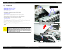
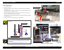
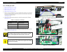
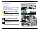
4.3.2 Damper ASSY
1. Execute ink discharge operation to discharge the ink from all the ink passages.
2. While pushing the cutter area gently, shift the carriage to the left about 2 cm to unlock
the carriage and then move the carriage to the printer center.
(See Figure 4-24)
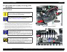
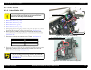
3. Loosen the one screw (CP(W): M3
×
6) securing the front end of the damper holder and
separate the Damper Unit from the print head.
(See Figure 4-25)
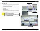
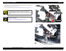
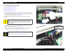
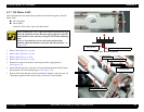
4. Disengage the three hooks of the Damper Holder and remove the Damper Holder.
(See Figure 4-28)
5. Pull out the relevant Damper ASSY from the Damper Holder, loosen the coupling
screw and separate the Damper ASSY from the ink tube.
(See Figure 4-29)
NOTE: Take care not to lose the O-ring inside the coupling screw.
Figure 4-28. Damper Holder Removal
Figure 4-29. Damper ASSY Removal
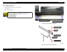
C H E C K
P O I N T
Execute ink discharge (“Ink Blowing”) before removing the
Damper ASSY.
Refer to “5.2.3.20 Clean Head (p.256)”.
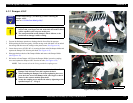
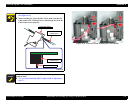
C A U T I O N
If you press on the transparent film on the damper's right side
surface with your fingers, the ink with which the inside is filled
will be expelled, so do not press on this part.
The transparent film on the damper's side is delicate, so be
careful not to damage it while working.
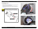
There is a hook 2 cm high at the center of the head. Install the
Damper Unit with care not to hit it against the hook.
When installing the Damper Unit, before tightening the screw,
press the lower area of the Damper with your fingers so that it
comes in close contact with the print head.
Secure the coupling screw and the ink tube by tightening at the
specified torque. (2 ~ 2.5 kg/f)
Hooks (3 positions)
Damper Holder
Damper ASSY
Damper Holder
Coupling screw