


EPSON Stylus Pro 7600/9600 Revision A
Disassembly & Assembly Disassembly and Assembly of Circuit Boards 205
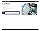
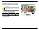
4.7 Disassembly and Assembly of Circuit Boards
This section describes the procedures for removing the Power Supply Board, Main
Board (C472MAIN) and AC Inlet.
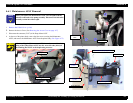
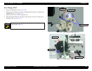
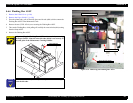
4.7.1 Power Supply Board
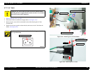
1.
Remove the Rear Cover. (p.166)
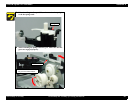
2. Disconnect the following connectors from the Power Supply Board:
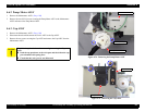
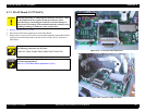
3. Remove the eight screws (CPS: M4
×
8) securing the Power Supply Board, and then
remove the Power Supply Board.
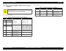
Figure 4-80. Power Supply Board Removal
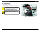
C A U T I O N
Unplug the AC power cable and wait at least five minutes before
removing the Power Supply Board to make sure there is no residual
power left in the board's capacitors.
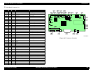
Table 4-5. Connectors on Power Supply Board
Connector No. Pins Color Connection Notes
CN001 3 White AC inlet Lock type
CN301 12 White C472MAIN Lock type
Screws (CPS: M4×8) ×8
CN001
CN301