


EPSON Stylus Pro 7600/9600 Revision A
Disassembly & Assembly Disassembly and Assembly of Ink Supply Mechanism 194
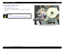
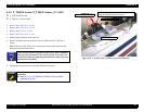
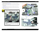
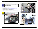
9. Remove one screw (CUPS: M3
×
6) and one screw (CUPS: M4
×
6) securing the I/H
Frame on the left side
.
(See Figure 4-65)
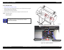
10. Remove seven screws (CUPS: M3
×
6) and two screws (CUPS: M4
×
6) securing the I/H
Frame on the top.
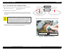
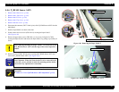
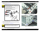
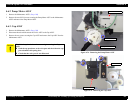
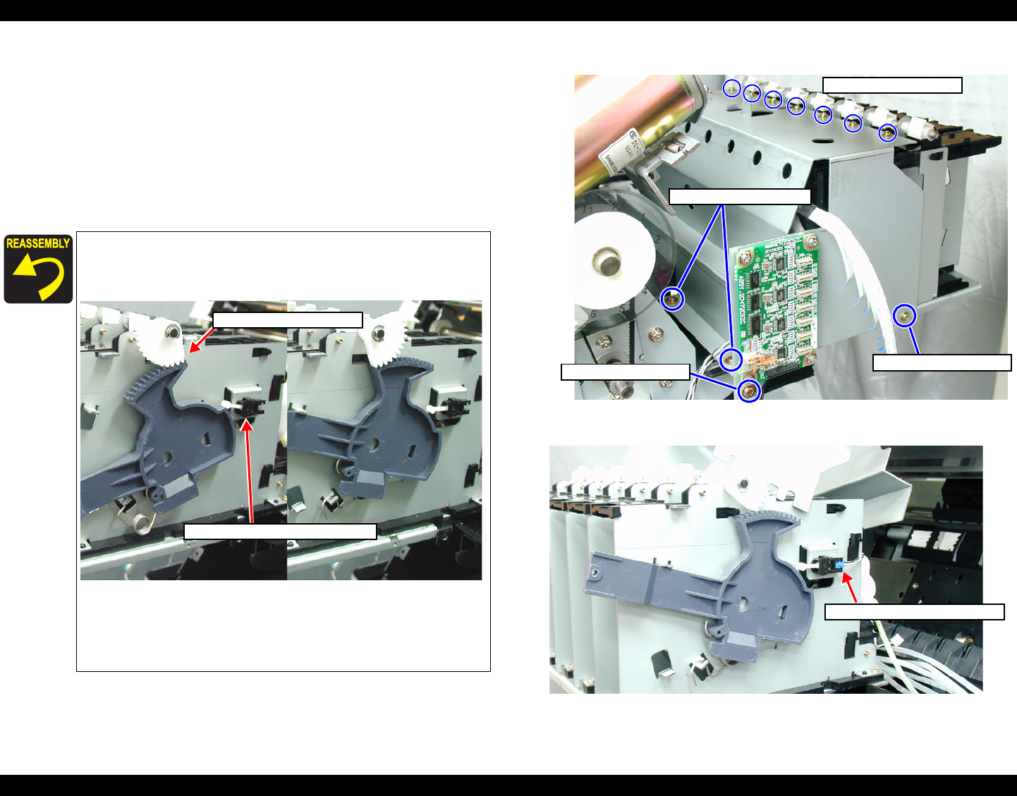
11. Lift the I/H Frame and disconnect the connector of the Release Sensor (I/H Lever).
(See Figure 4-66)
12. Remove the I/H Frame while paying attention to the connectors of the Cover Sensor
and Release Sensor (I/H Lever).
Figure 4-65. I/H Frame Removal 2/2
Figure 4-66. Release Sensor (I/H Lever) Removal
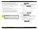
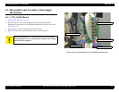
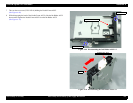
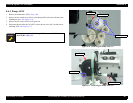
Before installing the I/H Frame, make certain that the gear of
the I/H Lever is engaged with the gear of the Cartridge Lock
Shaft and also that the Cover Sensor turns ON and OFF.
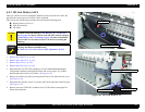
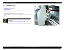
When installing the I/H Frame, make sure that the projections
on the I/H ASSY are fitted in the seven holes in the top plate
properly.
If the I/H ASSY is not installed properly, the ink cartridges
may not be recognized.
Check Release Sensor ON/OFF
Check gear engagement
Screws (CUPS: M3×6) ×7
Screws (CUPS: M4×6) ×2
Screw (CUPS: M4×6)
Screw (CUPS: M3×6) ×7
Connector of Release ASSY