


EPSON Stylus Pro 7600/9600 Revision A
Disassembly & Assembly Disassembly and Assembly of Carriage (CR) Mechanism 175
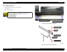
4.3.4 Cutter Section
4.3.4.1 Cutter Holder ASSY
1.
Remove the R Side Cover. (p.160)
2.
Remove the L Side Cover. (p.163)
3.
Remove the I/H Cover. (p.164)
4.
Remove the H Top Cover. (p.165)
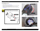
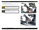
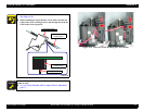
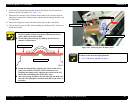
5. While pushing the cutter area gently, shift the carriage to the left about 2 cm to unlock
the carriage and then move the carriage to the printer center.
(See Figure 4-24)
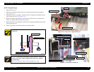
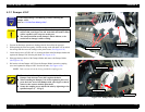
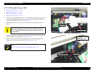
6. Remove one screw (CPPM3
×
6) securing the CR Board Guide, and remove three
screws (CP(W): M3
×
6) securing the ground line, washer (M3), and CR Board Guide.
(See Figure 4-30)
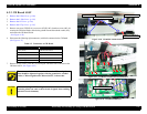
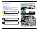
7. Disconnect the following three connectors on the CR Board.
(See Figure 4-31)
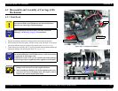
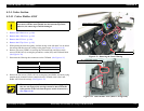
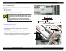
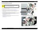
8. Remove the four screws (CP(W): M3
×
8) securing the Cutter Holder, and while paying
attention to the connector harness connected to the CR Board, remove the Cutter
Holder ASSY from the carriage.
(See Figure 4-33)
Figure 4-33. Removing the Cutter Housing
Figure 4-34. Cutter Holder ASSY (Back: Carriage Side)
C A U T I O N
When unlocking the carriage, do not move the carriage by about 2
cm or more with the cutter pushed into the innermost position;
otherwise, the cutter edge would be damaged.
Connector Type Connected to
5-Pin (white) CR Encoder Sensor
4-Pin (black) P_EDGE Sensor
2-Pin (white) Cutter Solenoid
The cutter cap and the CR lock kicker should be engaged. (If
they are not engaged, the carriage cannot be moved from the
home position to the left when the power switch is turned on.)
(See Figure 4-34)
Cutter Holder ASSY
Screws (CP(W): M3×8) ×4
Key engaged with carriage