


EPSON Stylus Pro 7600/9600 Revision A
Adjustment Mechanism Adjustment 266
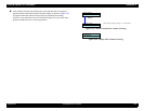
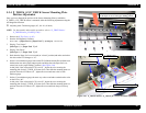
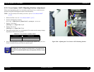
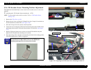
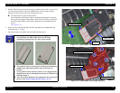
8. Set the 0.9-mm thickness gauge between the PF Grid Roller and the Driven Roller near
the detection arm on the paper transport path, and bring down the Paper Set Lever
toward you (to the “paper holding” position).
At this point, if the value on the LCD is not “11”, loosen the screw securing the
mounting plate for the P_THICK Sensor (right). Then slide the mounting plate to a
position where the LCD shows “11”, tighten the screw and remove the 0.9-mm
thickness gauge.
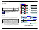
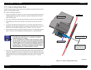
9. Set the 0.8-mm thickness gauge the same way as above and make certain that the value
on the LCD is “01”.
At this point, if the value on the LCD is not “01”, loosen the screw securing the
mounting plate for the P_THICK Sensor (right). Then slide the mounting plate to a
position where the LCD shows “01”, tighten the screw and check the previous step
again.
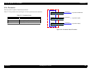
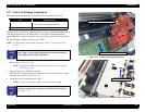
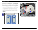
10. Turn the power switch Off, then after disconnecting the power cable, install the H Top
Cover.
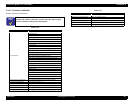
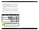
Table 5-30.
Mounting Plate Gauge Condition
LCD
Indication
P_THICK_0.3 Sensor Mounting
Plate (left)
0.3 mm
Paper thickness
0.3 mm or below
00
0.4 mm
Paper thickness
0.4
∼ 0.6 mm
01
P_THICK Sensor Mounting Plate
(right)
0.8 mm
0.9 mm
Paper thickness
0.7mm or above
11
–
Lever in “Up” position
(Paper released)
10
Lever in "Down" position
(Paper held)
00
C A U T I O N
Take care not to bend thickness gauges by, say, dropping.
This adjustment requires an accuracy to units of 0.1 mm.