


EPSON Stylus Pro 7600/9600 Revision A
Product Description Interfaces 91
1.6 Interfaces
1.6.1 Parallel Interface
1.6.1.1 Compatibility Mode
SPECIFICATION
Transmission mode: 8 bit parallel
Synchronization: By STROBE pulse
Handshaking: By BUSY and ACKNLG signal
Signal level: TTL level (IEEE1284Level 1 device)
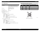
Adaptable connector: 57-30360(amphenol) 36 pin or equivalent
NOTE: It is recommended to use as short an interface cable as possible.
CONNECTOR PIN ASSIGNMENT AND SIGNALS
For these signals, twist-pair wires are used, with the return side connected to the signal
ground.
Note 1: “-” is prefixed to each signal which is active at “LOW” level.
2: In/Out refers to the direction of signal flow from the printer's point of view.
3: The “return side” means twist-pair return, which is connected to the signal GND. For
interface, each signal is connected with a twist-pair wire and the return side is also
connected. For protection against noise, this cable is shielded and connected to the
chassis GND for each of the center machine and the printer.
4: All the interface conditions are based on the TTL level standard. Each of the rise time
and fall time is 0.2
µs or less.
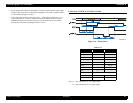
5: See Figure 1-19 for details of signal timing.
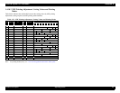
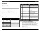
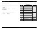
Table 1-53. Connector Pin Assignment and Signals (Compatibility)
Pin No.
Return
GND pin
Signal Name In/Out Function
119-STROBEIn
The strobe pulse. This signal is normally “HIGH” and
read-in of data is executed after turning “LOW”. The
pulse width required at the receive end is 0.5
µs or
more.
2 20 DATA0 In
The DATA0 through DATA7 signals represent data
bits 0 to 7, respectively. Each signal is at high level
when data is logical 1 and low level when data is
logical 0.
3 21 DATA1 In
4 22 DATA2 In
5 23 DATA3 In
6 24 DATA4 In
7 25 DATA5 In
8 26 DATA6 In
9 27 DATA7 In
10 28 -ACKNLG Out
This signal, when the signal level is “Low”, indicates
that the printer has received data and is ready to accept
the next data. The pulse width is 1
µs or 3 µs. (See
Figure 1-19)
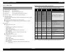
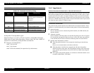
11 29 BUSY Out
This signal, when the level is “HIGH”, indicates that
the printer can not receive data. When the level is
“LOW”, the signal indicates that the printer can
accept data. This signal turns “HIGH” in one of the
following cases:
During data entry
In error status
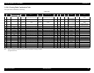
12 28 PE Out
This signal, when the level is “HIGH”, indicates
paper-out error. (Valid when ERROR = “LOW”)
13 28 SLCT Out
Always at “HIGH” level when the power to the printer
is on. Pulled up to +5 V via 1.0 kΩ.
14 30 -AFXT In Not used
31 30 -INIT In
The printer is initialized by input of a “LOW” pulse
whose width is 50
µs or more.
32 29 -ERROR Out
The “LOW” signal indicates that the printer is in error
status.
36 30 -SLIN In Not used
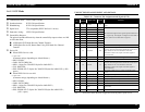
18 -- Logic H Out
Always at “HIGH” level. Pulled up to +5 V via 3.9
KΩ.
35 -- +5V Out
Always at “HIGH” level. Pulled up to +5 V via 1.0
kΩ.
17 -- Chassis GND - Chassis GND.
16,33
19-30
-- GND - Signal GND.
15,34 -- NC - Not used
Table 1-53. Connector Pin Assignment and Signals (Compatibility) (continued)
Pin No.
Return
GND pin
Signal Name In/Out Function