


EPSON Stylus Pro 7600/9600 Revision A
Operating Principles Print Mechanism Components 116
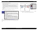
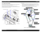
Cap assembly
When not printing, the print head (should) rest on the cap assembly to ensure that
the nozzles don't clog. Also, the print head is in the capped position during ink
charging, cleaning, and so on.
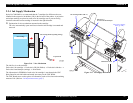
Flushing box
Flushing (dummy printing) is performed over the flushing box, and the flushed ink
flows through the pipe to the waste ink pads.
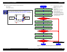
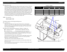
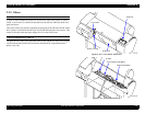
CR Lock Mechanism
If the carriage moves from the printable area to beyond the capping (CR_HOME)
position to the right, the carriage moving prevention lock is engaged. The CR lock
mechanism uses the cutter solenoid in common. When the cutter solenoid goes ON
in the capping position, the CR lock is released.
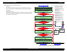
Maintenance Tank (Waste ink absorber)
NOTE: The Ink System Terms used in the above text are explained in the
following table.
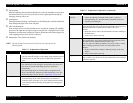
Table 2-7. Explanation of Operation
Operation Explanation
Carriage (CR) Lock • This is the carriage stop position when the power is Off.
• The time when the carriage is in the standby position (home position)
with the power On and with no paper loaded and no print data to
print.
Ink Initial Filling • This is the operation where the head is filled with ink for the first
time. When the first ink cartridge is inserted (after all 6 colors have
been inserted), the ink initial filling operation is performed
automatically.
• The initial filling flag is set when the printer is shipped from the
factory, then after this operation, the initial filling flag is reset. The
initial filling flag is also set after the “ Input Rank” (p233) is run.
Flushing • In order to prevent the viscosity of the ink inside the head nozzles
from increasing, the ink inside the flushing box is flushed out.
• Flushing is done when paper is set, when printing from the standby
state, during continuous printing, during paper Eject, during paper
cutting, etc.
Empty Suction
Operation
• After ink is sucked up, the remaining ink inside the cap is sucked up
and the ink adhering to the head nozzle surface is removed.
• Through flushing, etc., the ink that has accumulated in the cap is
sucked up and discharged.
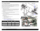
Wiping Operation The carriage is moved from right to left along the rubber side of the
wiper (the right half of the wiper plate) incorporated in the pump unit so
that the head surface is rubbed with the rubber of the wiper.
Purpose:
• Before ink suction, removes the ink and other substances adhering to
the head surface.
• Ensures close contact of the cap.
Rubbing Operation The carriage is moved from left to right along the felt side of the wiper
(the left half of the wiper plate) incorporated in the pump unit so that
the head surface is rubbed with the felt of the wiper.
For easy removal of adhering substances, the nozzle surface is wetted
before rubbing operation by suction of a small amount of ink.
Purpose:
• Removes ink and other substances adhering strongly to the head
surface.
• Ensures close contact of the cap.
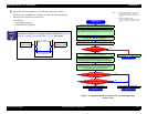
Capping In order to prevent the ink viscosity from increasing while it is being
kept, a rubber cap is placed over the print head nozzles when entering a
shutdown operation.
Table 2-7. Explanation of Operation (continued)
Operation Explanation