


EPSON Stylus Pro 7600/9600 Revision A
Disassembly & Assembly Summary 154
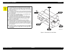
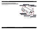
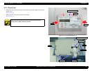
Figure 4-1. Directional View of the Printer
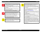
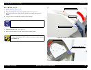
C A U T I O N
In reassembly, place the wiring of electric parts in specified
positions. (If wiring is located in places other than specified,
cables can come in contact with a sharp edge or the anti-noise
margin may lessen.)
As necessary, if you remove each cover and operate the printer,
care should be taken not to get injured by the operation of the
drive system units.
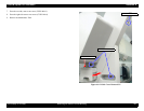
The cutter blade is extremely sharp, so care should be taken
not to injure yourself when handling it.
An ultra-hardened blade is used for the cutter blade, and
physically, it is extremely brittle material, so care should be
taken not to bump it against any of the metal parts of the
printer, etc. and damage it.
When performing service operations on items which are
controlled as after service parts but which no procedures have
been provided for, the state of the parts should be observed
closely before beginning the operation to get a thorough idea of
how to proceed.
If you have to loosen a screw that has blue screw-lock applied
to its head, make sure you apply blue screw-lock again when
reassembling.
Top
Rear
Front
Bottom
R
L