


EPSON Stylus Pro 7600/9600 Revision A
Product Description Interfaces 94
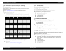
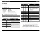
1.6.1.3 ECP Mode
SPECIFICATION
Transmission mode: IEEE-1284ECP mode
Synchronization: IEEE-1284 specification
Handshaking: IEEE-1284 specification
Signal level: TTL compatible (IEEE1284Level 1 device)
Data trans. timing: IEEE-1284 specification
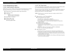
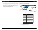
Extensibility Request:
The printer responds affirmatively when the extensibility request values are 10H
or 04H, that mean,
10H Request ECP Mode Reverse Channel Transfer.
14H Request Device ID; Return Data Using ECP Mode Rev Channel
Transfer.
Device ID:
When IEEE1284.4 is valid
• <xx><xx>
(Character strings, depending on <Model Name>)
• MFG: EPSON;
• CMD: ESCPL2,BDC,D4;
• MDL: <Stylus Pro 7600-DYE/Stylus Pro 9600-DYE> ;
• CLS: PRINTER;
• DES: EPSON<SP>T<Stylus Pro 7600-DYE/Stylus Pro 9600-DYE>;(<SP>:
space)
When IEEE1284.4 is not valid
• <xx><xx>
(Character strings, depending on <Model Name>)
• MFG: EPSON;
• CMD: ESCPL2,BDC;
• MDL: <Stylus Pro 7600-DYE/Stylus Pro 9600-DYE>;
• CLS: PRINTER;
• DES: EPSON<SP>T<Stylus Pro 7600-DYE/Stylus Pro 9600-DYE>;
(<SP>: space)
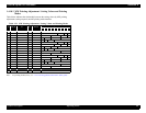
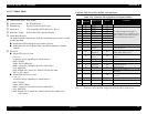
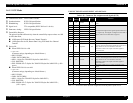
CONNECTOR PIN ASSIGNMENT AND SIGNALS
Note "*": In/Out refers to the direction of signal flow from the printer's point of view.
Table 1-56. Connector Pin Assignment and Signals (ECP)
Pin
No.
Return
GND Pin
Signal Name In/Out* Function
119HostClk In
Data or address information are transferred from a host to a
printer.
2 20 DATA0 In
The DATA0 through DATA7 signals represent data bits 0
to 7, respectively. Each signal is at high level when data is
logical 1 and low level when data is logical 0.
3 21 DATA1 In
4 22 DATA2 In
5 23 DATA3 In
6 24 DATA4 In
7 25 DATA5 In
8 26 DATA6 In
9 27 DATA7 In
10 28 PeriphClk Out Data is transferred from a printer to a host.
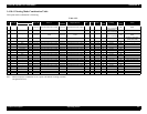
11 29 PeriphAck Out
A printer uses this signal for a flow control of forward
direction. Also this signal offers the data bit 9 that use it to
judge whether or not it is information command
information or data to be output on the data signal of
reverse direction.
12 28 nAckReverse Out A printer does drive to Low and approve nReverseRequest.
13 28 Xflag Out X-flag signal and reverse channel transfer data bit 1 or 5.
14 30 HostAck In
A host uses this signal for a flow control of reverse
direction. Also this signal offers the data bit 9 that use it to
judge whether or not it is information command
information or data to be output on the data signal of
forward direction.
31 30 nReverseRequest In
This signal is made a low, to change a channel toward
reverse.
32 29 nPeriphReques Out This signal uses to produce a host interrupt.
36 30 1284-Active In 1284 active signal. “HIGH” in ECP mode
18 -- PeriphLogic Out Always “HIGH”. Pulled up to +5 V via 3.9 K ohm resistor.
35 -- +5V Out Always “HIGH”. Pulled up to +5 V via 1.0 K ohm resistor.
17 -- Chassis GND -- Chassis GND.
16,33
19-30
-- GND -- Signal GND.
15,34 -- NC -- Not connected.