


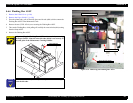

EPSON Stylus Pro 7600/9600 Revision A
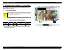
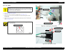
Disassembly & Assembly Disassembly and Assembly of Circuit Boards 208
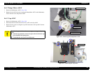
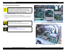
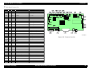
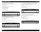
Main Board Connector List
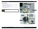
Figure 4-85. Connector Locations
CN.No. Pins Color Connection Remarks
CN1 12 White P/S board Lock type
CN2 16 PANEL FFC, lock type
CN3 36 H-UDI36
CN4 5 Yellow D/A_OUT (
Not used
)
CN5 90 ROM_DIMM
CN6 21 CSIC
FFC
CN7 5 Red S_I/O(DEBUGER) (
Not used
)
CN8 24 CR_FFC1
FFC, lock type
CN9 24 CR_FFC3 FFC, lock type
CN10 24 CR_FFC2
FFC, lock type
CN11 36 IEEE1284 (parallel port)
CN12 4 USB (
Not used
)
CN13 36 TYPE_B
CN14 3 White CR_MOT Lock type, with relay connector
CN15 2 White PF_MOT
Lock type, with relay connector
CN16 5 White PF_ENC
CN17 4 White PUMP_MOT With relay connector
CN18 2 Blue P/S_FAN
CN19 2 Black FAN1
With relay connector
CN20 2 Yellow FAN2 With relay connector
CN21 2 Red FAN3
* Stylus Pro 9600 only
CN22 3 Blue P_THICK0.3
CN23 3 Yellow COVER_L
CN24 3 White CR_ORG
CN25 3 Black I/H_LEVER (
Not used
)
CN26 3 Red P_THICK
CN27 4 Black P_REAR
CN28 4 Yellow P_FRONT (
Not used
)
CN29 4 Red HD_SLID
CN30 15 ROLL_UNIT (option unit)
* Stylus Pro 9600 only
CN31 2 White H_FAN
CN33 3 White RESET
CN35 4 USB2.0
Right side (AC side)
CN36 8 IEEE1394 (
Not used
)
CN37 2 HDD_PS (
Not used
)