3-30 Sun StorEdge 5310 NAS Troubleshooting Guide • December 2004
6. If applicable, repeat for all other modules in the storage array.
End Of Procedure
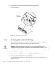
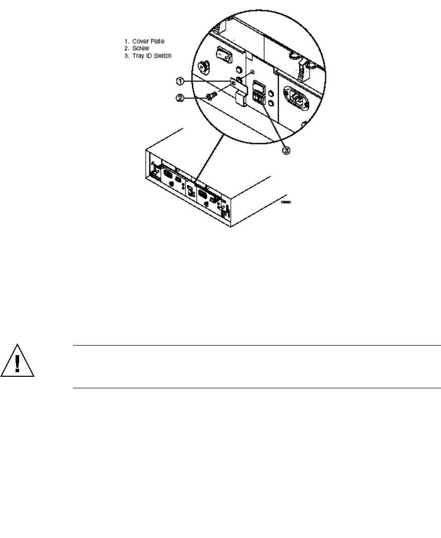
FIGURE 3-17 Setting the Tray ID Switch
3.2.4 Verifying the Link Rate Setting
Use the following procedure to verify the Link Rate setting if a link rate problem is
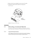
indicated. Figure 3-18 shows the location of the Link Rate switch.
Caution – Electrostatic discharge damage to sensitive components. To prevent
electrostatic discharge damage to the module, use proper antistatic protection when
handling the module components.
1. Put on antistatic protection.
2. Remove the screw and the switch cover from the Link Rate switch.
3. Verify that the Link Rate Switch is set to 2 Gb/s.
The Link Rate switch is not active. This switch is pre-set to 2 Gb/s at the factory, and
defaults to 2 Gb/s.


