2-34 Sun StorEdge 5310 NAS Troubleshooting Guide • December 2004
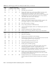
5Ah G R G R 8254 timer test on channel 2.
5Ch G A Off R Enable 8042. Enable timer and keyboard IRQs. Set video mode
initialization before setting the video mode is complete.
Configuring the monochrome mode and color mode settings next.
5Eh G A G R Initialize PCI devices and motherboard devices. Pass control to
video BIOS. Start serial console redirection.
60h Off R R Off Initialize memory test parameters.
62h Off R A Off Initialize AMI display manager module. Initialize support code
for headless system if no video controller is detected.
64h Off A R Off Start USB controllers in chipset.
66h Off A A Off Set up video parameters in BIOS data area.
68h G R R Off Activate ADM: the display mode is set. Displaying the power-on
message next.
6Ah G R A Off Initialize language module. Display splash logo.
6Ch G A R Off Display sign on message, BIOS ID, and processor information.
6Eh G A A Off Detect USB devices.
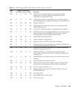
70h Off R R R Reset IDE Controllers.
72h Off R A R Displaying bus initialization error messages.
74h Off A R R Display setup message: the new cursor position has been read and
saved. Displaying the hit setup message next.
76h Off A A R Ensure timer keyboard interrupts are on.
78h G R R R Extended background memory test start.
7Ah G R A R Disable parity and NMI reporting.
7Ch G A R R Test 8237 DMA controller: the DMA page register test passed.
Performing the DMA controller 1 base register test next.
7Eh G A A R Initialize 8237 DMA controller: the DMA controller 2 base register
test passed. Programming DMA controllers 1 and 2 next.
80h R Off Off Off Enable mouse and keyboard: the keyboard test has started.
Clearing the output buffer and checking for stuck keys. Issuing
the keyboard reset command next
82h R Off G Off Keyboard interface test: A keyboard reset error or stuck key was
found. Issuing the keyboard controller interface test command
next.
TABLE 2-16 POST Progress LED Code Table (Port 80h Codes) (Continued)
POST
Code
Diagnostic LED Decoder
(G = green, R = red, A = amber) Description


