


www.ti.com
7.6.2WarmReset(RESETPin)
SM320C6455-EP
FIXED-POINTDIGITALSIGNALPROCESSOR
SPRS462B–SEPTEMBER2007–REVISEDJANUARY2008
allthesystemclocksareinvalidatthispoint.
–TheRESETSTATpinstaysasserted(low),indicatingthedeviceisinreset.
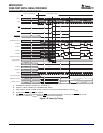
3.ThePORpinmaynowbedeasserted(drivenhigh).
WhenthePORpinisdeasserted,theconfigurationpinvaluesarelatchedandthePLLcontrollers
changetheirsystemclockstotheirdefaultdivide-downvalues.PLL2istakenoutofresetand
automaticallystartsitslockingsequence.Otherdeviceinitializationisalsostarted.
4.Afterdeviceinitializationiscomplete,theRESETSTATpinisdeasserted(drivenhigh).Bythistime,
PLL2hasalreadycompleteditslockingsequenceandisoutputtingavalidclock.Thesystemclocksof
bothPLLcontrollersareallowedtofinishtheircurrentcyclesandthenpausedfor10cyclesoftheir
respectivesystemreferenceclocks.Afterthepausethesystemclocksarerestartedattheirdefault
divide-bysettings.
5.Thedeviceisnowoutofreset,deviceexecutionbeginsasdictatedbytheselectedbootmode(see
Section2.4,BootSequence).
NOTE
Tomostofthedevice,resetisde-assertedonlywhenthePORandRESETpinsareboth
de-asserted(drivenhigh).Therefore,inthesequencedescribedabove,iftheRESETpin
isheldlowpastthelowperiodofthePORpin,mostofthedevicewillremaininreset.The
onlyexceptionbeingthatPLL2istakenoutofresetassoonasPORisde-asserted
(drivenhigh),regardlessofthestateoftheRESETpin.TheRESETpinshouldnotbetied
togetherwiththePORpin.
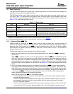
AWarmResethasthesameeffectsasaPower-onReset,exceptthatinthiscase,thetestandemulation
logicandPLL2arenotreset.
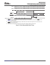
ThefollowingsequencemustbefollowedduringaWarmReset:
1.HoldtheRESETpinlowforaminimumof24CLKIN1cycles.Withintheminimum24CLKIN1cycles.
WithinthelowperiodoftheRESETpin,thefollowinghappens:
–TheZgrouppins,lowgrouppins,andthehighgrouppinsaresettotheirresetstatewithone
exception:
ThePCIpinsarenotaffectedbywarmresetifthePCImodulewasenabledbeforeRESETwent
low.Inthiscase,PCIpinsstayatwhatevertheirvaluewasbeforeRESETwentlow.
–Theresetsignalsflowtotheentirechip(excludingthetestandemulationlogic),resettingmodules
thatuseresetasynchronously.
–ThePLL1controllerisresettherebyswitchingbacktobypassmodeandresettingallitsregistersto
theirdefaultvalues.PLL1isplacedinresetandloseslock.ThePLL1controllerclocksstartrunning
atthefrequencyofthesystemreferenceclock.Theclocksarepropagatedthroughoutthechipto
resetmodulesthatuseresetsynchronously.
–ThePLL2controllerisresettherebyresettingallitsregisterstotheirdefaultvalues.ThePLL2
controllerclocksstartrunningatthefrequencyofthesystemreferenceclock.PLL2isnotreset,
thereforeitremainslocked.
–TheRESETSTATpinbecomesactive(low),indicatingthedeviceisinreset.
2.TheRESETpinmaynowbereleased(driveninactivehigh).
WhentheRESETpinisreleased,theconfigurationpinvaluesarelatchedandthePLLcontrollers
immediatelychangetheirsystemclockstotheirdefaultdivide-downvalues.Otherdeviceinitialization
isalsostarted.
3.Afterdeviceinitializationiscomplete,theRESETSTATpingoesinactive(high).Allsystemclocksare
allowedtofinishtheircurrentcyclesandthenpausedfor10cyclesoftheirrespectivesystemreference
clocks.Afterthepausethesystemclocksarerestartedattheirdefaultdivide-bysettings.
4.Thedeviceisnowoutofreset,deviceexecutionbeginsasdictatedbytheselectedbootmode(see
SubmitDocumentationFeedbackC64x+PeripheralInformationandElectricalSpecifications129