


Configuring Communication
93
VG-Series Modero Touch Panels
Configuring Communication
Overview
Communication between the Modero panel and the Master is done using either USB or ETHERNET
(DHCP or Static IP). Ethernet communication can be achieved through either a direct connection
(Ethernet) or through the use of the optional NXA-PCI80211G wireless interface card.
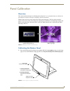
Modero Setup and System Connection
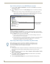
1. Press the grey Front Setup Access button for 3 seconds to open the Setup page (FIG. 71).
2. Press the Protected Setup button (located on the lower-left of the panel page) to open the Protected
Setup page and display an on-screen keypad.
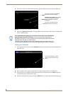
3. Enter 1988 into the Keypad’s password field and press Done when finished.
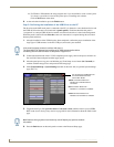
4. Press the red Device Number field to open the Device Number keypad (FIG. 72).
5. Enter a Device Number value for the panel into the Device Number Keypad.
The default value is 10001 and the range is from 1 - 32000.
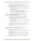
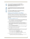
USB input devices must be plugged into the rear or side USB connectors before the
G4 panel is powered-up. The panel will not detect a USB connection of this type until
after the unit cycles power.
Before commencing, verify you are using the latest NetLinx Master and Modero panel
firmware. Verify you are using the latest versions of AMX’s NetLinx Studio and
TPDesign4 programs.
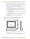
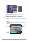
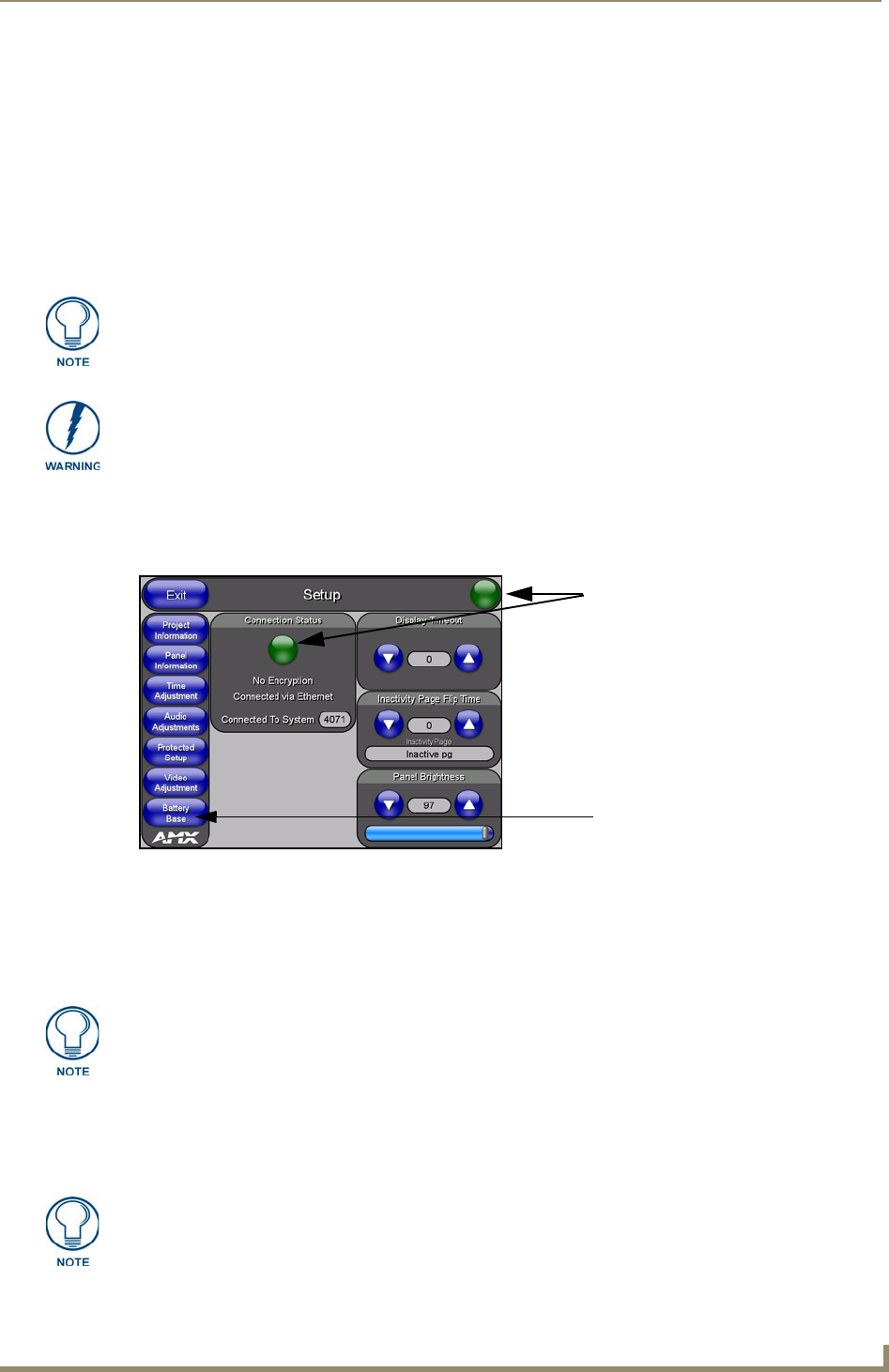
FIG. 71 Setup page
Battery Base button doesn’t appear
until NXT is connected to a BASE/B
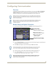
Connection Status
Red Connection Status icon -
Green Connection Status icon -
indicates no connection to a Master
indicates communication to a Master
indicates an unreliable
network connection
Yellow Connection Status icon -
Clearing Password #5, from the initial Password Setup page, removes the need for
you to enter the default password before accessing the Protected Setup page.
When using multiple panels within a NetLinx System, remember to assign unique
Device Number values to each panel so that all assigned panels appear in the
System listing for the target Master.