


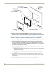
Installation Procedures: 12" and 15" Panels
70
VG-Series Modero Touch Panels
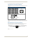
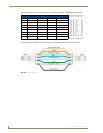
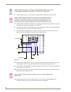
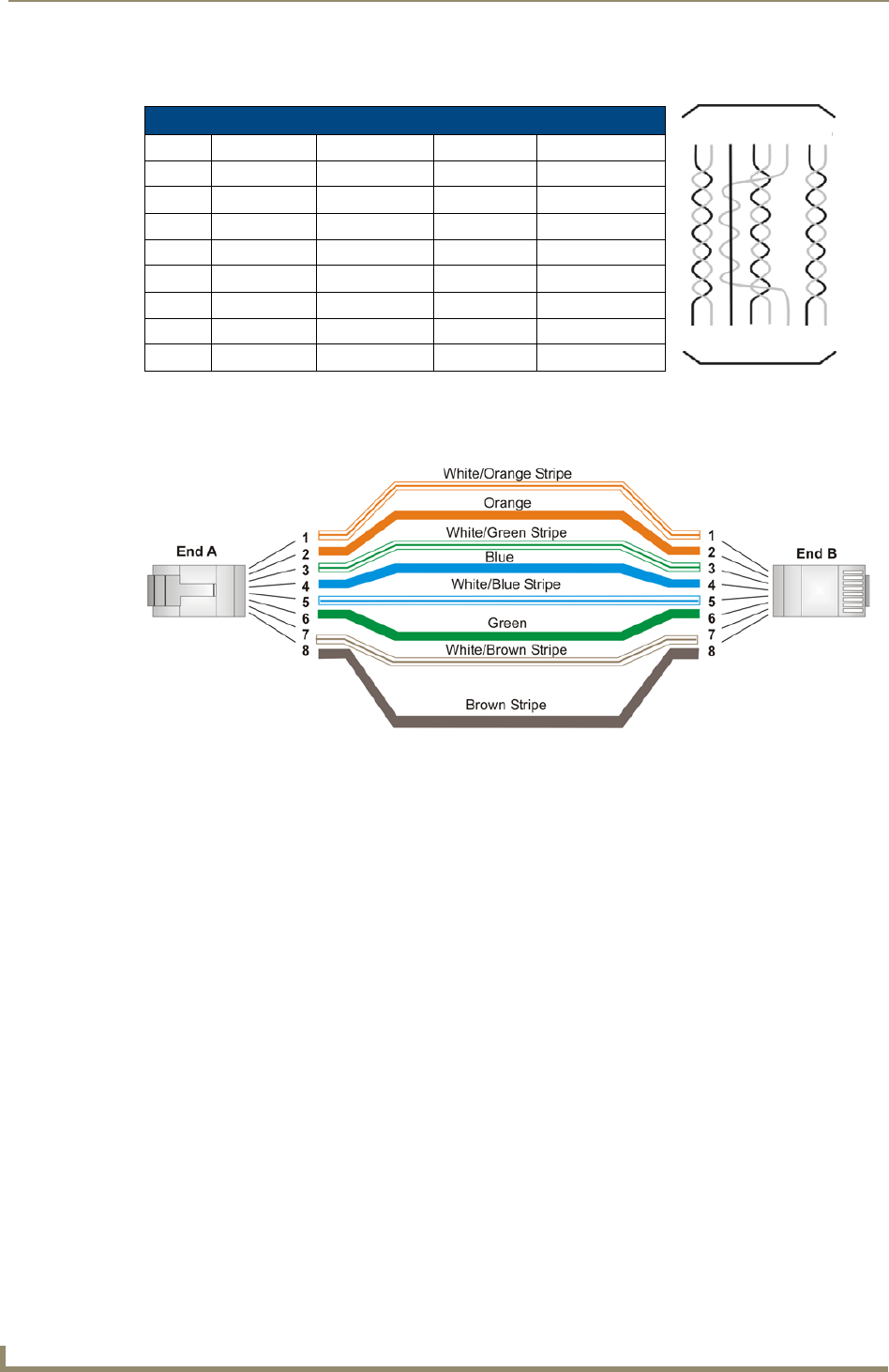
The following table lists the pinouts, signals, and pairing associated with the Ethernet connector.
FIG. 50 diagrams the RJ-45 pinouts and signals for the Ethernet RJ-45 connector and cable.
Ethernet RJ-45 Pinouts and Signals
Pin Signals Connections Pairing Color
1 TX + 1 --------- 1 1 --------- 2 Orange-White
2 TX - 2 --------- 2 Orange
3 RX + 3 --------- 3 3 --------- 6 Green-White
4 no connection 4 --------- 4 Blue
5 no connection 5 --------- 5 Blue-White
6 RX - 6 --------- 6 Green
7 no connection 7 --------- 7 Brown-White
8 no connection 8 --------- 8 Brown
FIG. 50
RJ-45 wiring diagram
123 456 78
123 456 78