


Installation Procedures: 17" Panels
71
VG-Series Modero Touch Panels
Installation Procedures: 17" Panels
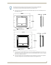
Overview
NXT panels are mounted onto flat (horizontal) surfaces in either a stand-alone or combo (NXT atop an
NXA-BASE/B battery base) configuration. NXD panels are installed into either a pre-wall surface (using
the CB-TP17 conduit/wallbox) or a solid surface (using either solid surface or drywall screws).
Unpacking the Panel
1. Inspect and confirm the contents of the shipment box to verify that you have all specified parts.
Refer to the Specifications section on page 12 for more information about included accessories and
other AMX equipment.
2. Carefully remove the panel from the shipping box.
3. Carefully peel the protective plastic cover from the LCD.
Installing the Internal Components
Installation of the internal components such as the NXA-PCI80211G Wireless card and NXA-RGB
Interface card are described in detail within the following sections:
Step 2: Install the 802.11g mini-PCI Wireless Card section on page 38.
Step 3: Install the NXA-RGB Card Component (NXT) section on page 39.
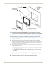
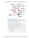
Upgrading the Back Box with the MB-TP17 VESA Housing
Upgrading the existing back box with the new VESA Mounting Kit (FG033-50) requires 3 main
processes:
Removing the pre-existing back box and installing the new VESA back box.
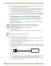
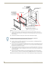
Threading cables through the strain relief grommet opening in the rear plastic cover.
Finalizing the installation of the NXD (with VESA back box and cables) into the plastic cover,
securing both components, and finalizing the strain relief grommet installation.
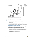
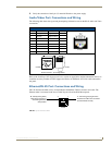
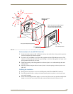
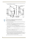
Removing the Original Modero Back Box
1.
Detach all connectors from the side of the touch panel.
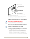
2. Remove the magnetic faceplate from the NXD-1700VG unit by gripping the faceplate and pulling
outwards while applying a small amount of pressure to remove it from the main unit.
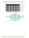
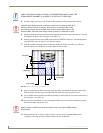
3. Place the LCD face-down on a soft cloth to expose the back of the panel and prevent scratching of
the LCD.
If the protective plastic LCD cover is not removed, the panel may not respond
properly to touch points on the LCD or allow proper screen calibration.
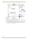
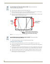
The new MB-TP17 Universal VESA Mounting Box uses a standard VESA installation
pattern of 75 mm between holes. VESA mounts that conform to this pattern can be
used on the MB-TP17 Housing.