


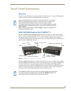
Touch Panel Accessories
25
VG-Series Modero Touch Panels
Wiring the NXA-AVB/RGB for Balanced Audio
Professional audio equipment will often use balanced audio inputs and outputs, usually on 3-pin "XLR"
connectors. A balanced audio signal consists of a pair of wires carrying the audio signal in anti-phase
with each other (if one wire carries a positive voltage, the other carries an equal and opposite negative
voltage).
The advantage of balanced audio over unbalanced audio is its ability to reject external interference added
as the signal is carried over the wire. The receiving equipment takes the voltage difference between the
two wires as the input signal. Interference will usually get added to both wires equally, and so gets
cancelled by the receiving equipment.
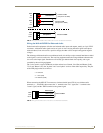
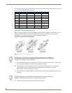
The 3 wires used in a typical XLR lead are often referred to as Ground, Live (Hot) and Return (Cold).
"Live" and "Return" carry the "in-phase" and "out-of-phase" versions of the audio respectively. The pins
of the XLR plug/socket are as follows:
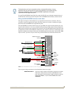
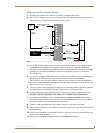
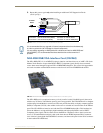
When connecting the MIC OUT connector to a balanced audio input (FIG. 6), use all three audio
terminals (+, -, and GND), then connect the "+" terminal to the "live" signal, the "-" terminal to the
"return" signal, and the "GND" terminal to the ground signal.
FIG. 5
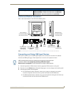
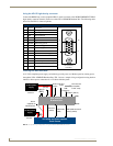
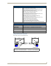
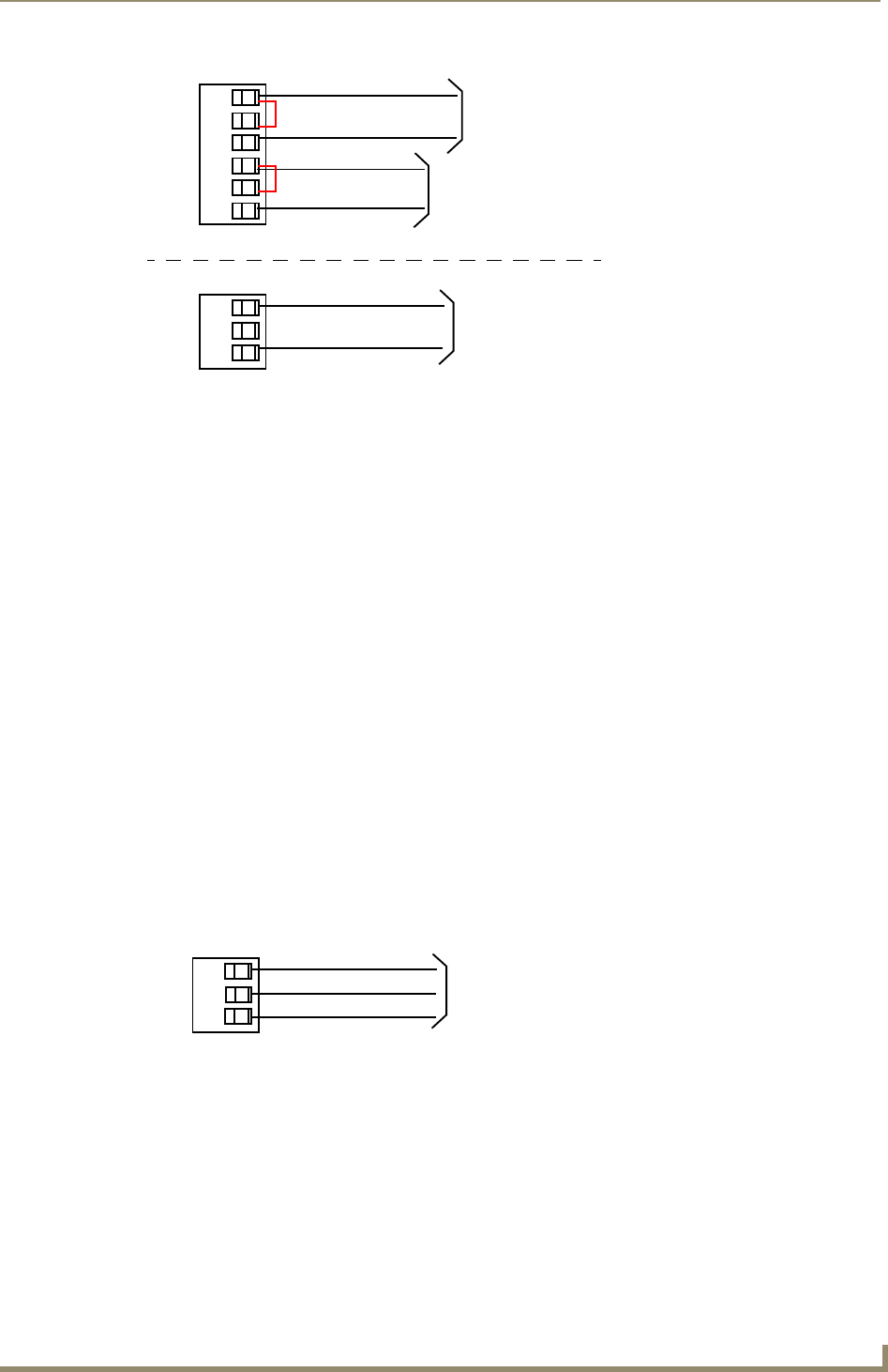
Wiring the rear AUDIO IN and MIC OUT for use with Unbalanced Audio
• X = Ground
• L = Live (Hot)
• R = Return (Cold)
FIG. 6
Wiring the rear MIC OUT connector for use with Balanced Audio
Unbalanced IN
GND
IN-
IN+
GND
IN-
IN+
Left Channel
Right Channel
(Jumper IN- to GND)
Unbalanced OUT
GND
OUT-
OUT+
Microphone
Unbalanced IN
(Jumper IN- to GND)
AUDIO IN
MIC OUT
Balanced OUT
GND
OUT-
OUT+
Ground signal
Return signal
Line signal