


Touch Panel Accessories
38
VG-Series Modero Touch Panels
6. In a single motion, carefully pull the outer housing up and then out (away from the LCD panel) to
expose the internal circuit board (FIG. 19). The NXA-RGB card is available within both the
optional RGB Kit and NXA-RGBKIT upgrade.
7. Unscrew the Stereo Output nut from the Stereo Output jack.
8. Firmly grab the existing connector plate and slide it up and away from the base. This part is later
replaced with the RGB connector plate.
Step 2: Install the 802.11g mini-PCI Wireless Card
1.
Discharge any static electricity from your body by touching a grounded metal object.
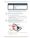
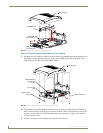
2. Locate the mini-PCI card connector on the main board (FIG. 16 and FIG. 17).
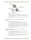
3. Carefully remove the gold-tipped terminal ends of the antenna from their factory default connectors
on the main board. The antenna is secured at this location to restrict its movement prior to
connection to a wireless card.
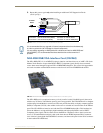
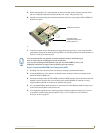
4. Firmly grasp the NXA-PCI80211G mini-PCI card (from the edges) and insert the pins (at a 25°
angle) into the opening on the connector (FIG. 18).
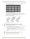
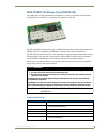
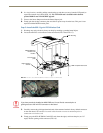
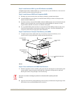
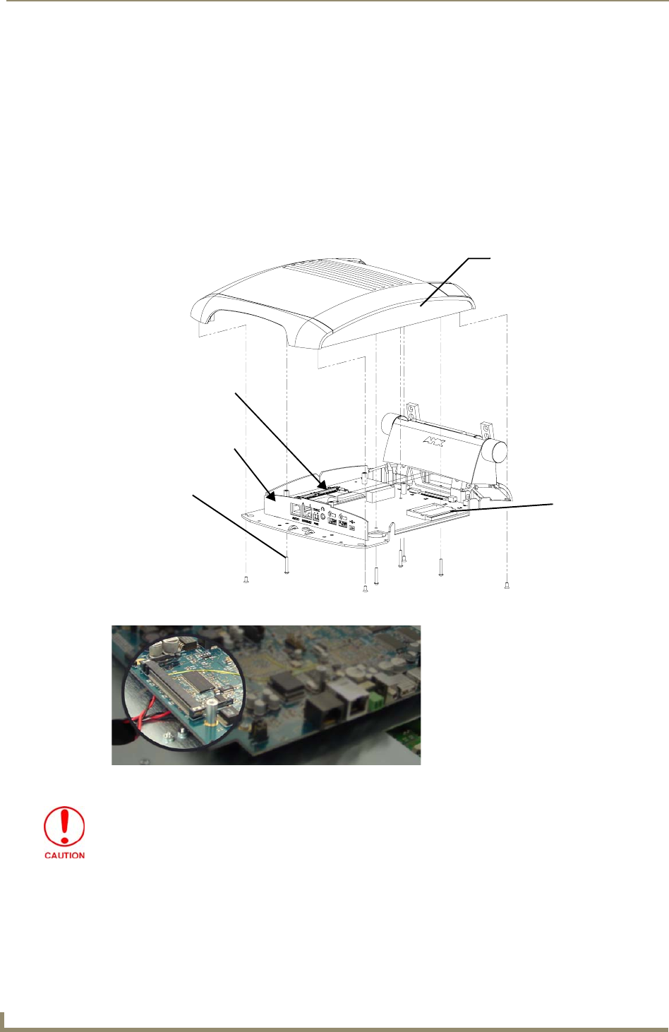
FIG. 16 Location of the NXA-PCI80211G wireless card on the NXT board
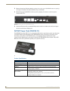
FIG. 17 Location of the mini-PCI card connector on main board
I/O connector
Compact Flash card
Outer Housing
plate
Eight Housing
Screws
NXA-PCI80211G
wireless card
location
If you have previously installed an NXA-RGB card, it must first be removed prior to
gaining access to the mini-PCI connector on the board.