


Displaying Stream Content
174
VG-Series Modero Touch Panels
14. Click the Apply button to save the encoding profiles to the MAX-CSE.
Step 3: Configuring the MAX-CSE audio/video inputs
1.
Complete the MAX-CSE connection and wiring procedures outlined within the Wiring the
MAX-CSE connectors and cables section of the MAX-CSE Instruction Manual.
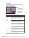
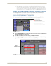
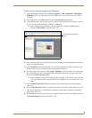
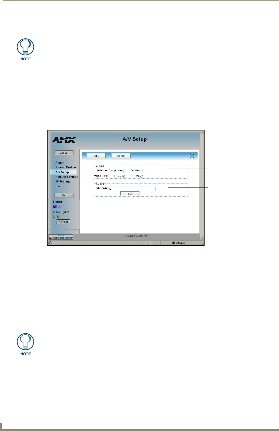
2. Access the A/V Setup page (FIG. 131) by clicking the A/V Setup link from within the Navigation
frame. This page provides the user with the ability to select the source of the incoming video signal
(from either the rear Composite or S-Video port), the format of the incoming video (NTSC/PAL),
and the gain given to the incoming audio signal.
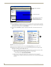
3. From within the Video section of this page, check off the appropriate Video In and Video Port radio
boxes which correspond to both the type of video signal being used and its associated format.
For the purpose of these procedures, we’ve chosen to feed an NTSC signal into the rear
Composite video connector. As a result, a user should "check-off"/select both the Composite
and NTSC radio boxes.
4. If you are feeding a microphone audio signal into the rear MAX-CSE microphone connector, you
could use the Microphone Gain field to enter an audio level (0 - 99) associated with the gain used by
the rear microphone input.
5. Click the Apply button to save the encoding profiles to the MAX-CSE.
If using RTP, both the Target Port and Target Audio Port must be different and
should use even numbers.
FIG. 131 A/V Setup page
Video Port and Video Format
Mic Gain value for incoming
audio signal
At any time, the user can choose to mute the incoming microphone signal by either
toggling the state of the Microphone icon located at the top of the page or entering a
value of zero into the Mic Gain field.