


Touch Panel Accessories
39
VG-Series Modero Touch Panels
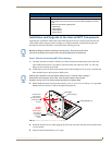
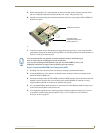
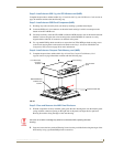
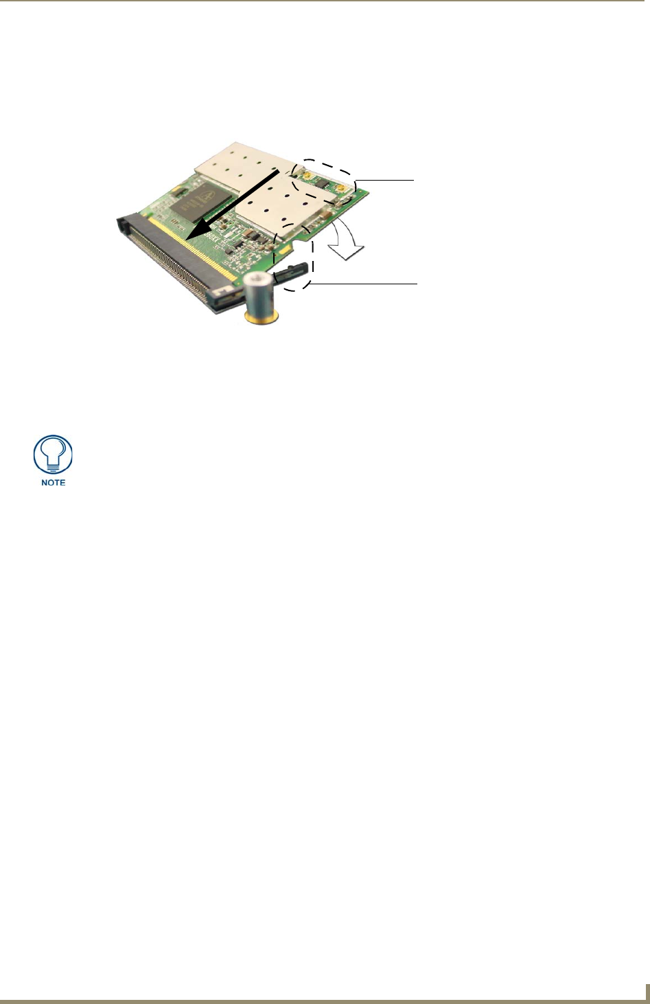
5. While maintaining the 25° angle alignment on the new module, push it in firmly until the contact
pins are completely inside the connector and the card "snaps" into place (FIG. 18).
6. Push the card downward (to the main board) until the side braces snap atop the NXA-PCI80211G
and hold it in place.
7. Locate the terminal ends of the antennas and apply downward pressure to "snap" them onto their
gold-tipped counterparts on the mini-PCI card (FIG. 18). Carefully push down on each connector to
verify it is securely joined to the card.
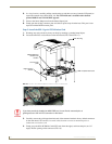
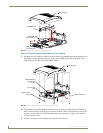
Step 3: Install the NXA-RGB Card Component (NXT)
1.
Discharge any static electricity from your body by touching a grounded metal object.
2. Locate the RGB card’s slot connector on the main board and align it with its counterpart on the
bottom of the NXA-RGB card.
3. Carefully, but firmly, insert the NXA-RGB card into the RGB connector slot on the main board until
both the card rests atop the four raised securing holes and the RGB RJ-45 connector is evenly
aligned with the other RJ-45 connectors on the back of the panel.
4. Use a grounded Phillips-head screwdriver to secure the four NXA-RGB pan-head securing screws
to the raised securing holes on the main board.
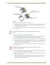
5. To complete the upgrade process, either upgrade the remaining component (Step 3) or close and
re-secure the enclosure using the procedures in Step 5: Close and Resecure the NXT Panel
Enclosure section on page 41.
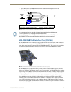
FIG. 18 Installation of the mini-PCI card connector on main board
Connection point
between the braces and
the mini-PCI card
Antennas connectors
It is recommended that any upgrade of internal equipment be done simultaneously in
order to reduce the risk of damage to internal components.
If you are also installing an NXA-RGB card (as part of an NXA-RGBKIT), refer to the
installation procedures on page 22 before replacing the outer housing.