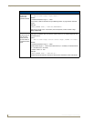
Installation Procedures: 17" Panels
72
VG-Series Modero Touch Panels
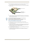
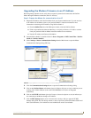
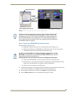
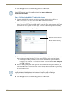
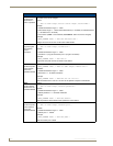
4. Unscrew the Stereo Output nut from the Stereo Output jack.
5. Remove the I/O connector plate by using a grounded Phillips-head screwdriver to remove the two
screws and slide the I/O connector plate away from the back box housing.
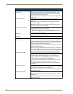
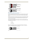
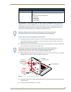
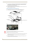
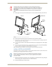
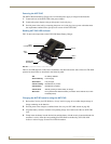
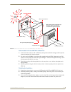
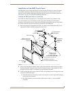
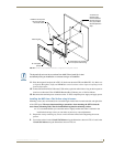
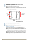
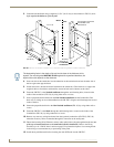
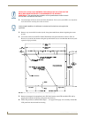
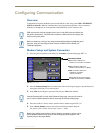
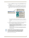
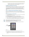
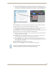
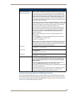
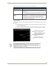
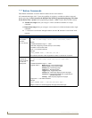
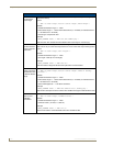
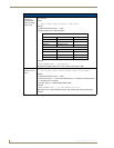
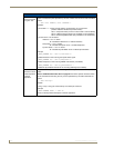
6. Remove the four pan-head Housing Screws from the rear of the NXD unit (FIG. 51). These screws
secure the back box to the internal panel casing.
7. Lift the back box housing to separate it from the internal panel casing.
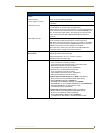
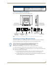
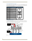
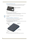
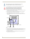
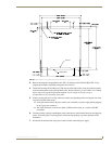
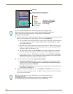
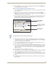
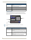
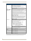
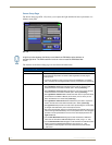
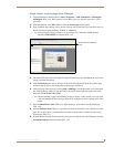
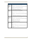
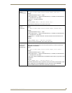
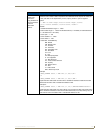
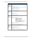
Installing the MP-TP17 Back Box
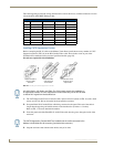
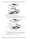
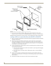
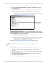
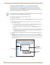
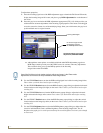
1.
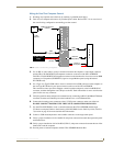
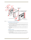
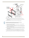
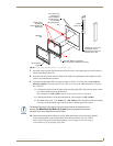
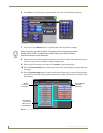
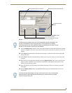
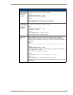
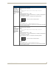
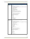
Unscrew the four pan-head Housing Screws (#8-32) from the MB-TP17 rear plastic cover.
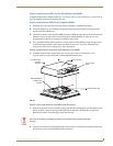
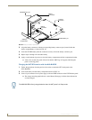
2. Gently place the MB-TP17 back box over the internal panel casing (with the cable routing hole on
the right-side of the panel).
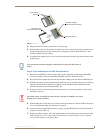
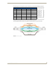
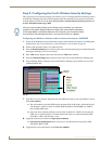
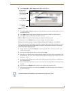
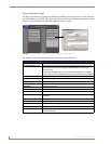
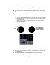
3. Re-install and secure the four pan-head Housing Screws into their pre-drilled holes along the edges
of the MB-TP17 back box (FIG. 52) and secure them using a grounded Phillips-head screwdriver.
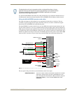
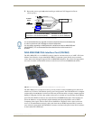
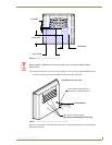
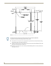
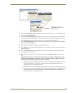
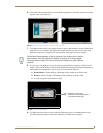
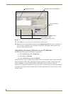
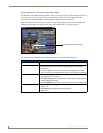
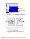
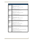
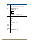
4. Place the I/O connector plate back over the connector opening and align the connector locations.
5. Resecure the I/O connector plate (using a grounded Phillips-head screwdriver) and resecure the
Stereo Output nut on the Stereo Output jack.
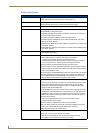
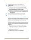
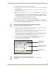
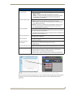
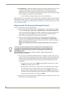
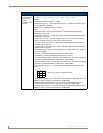
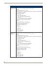
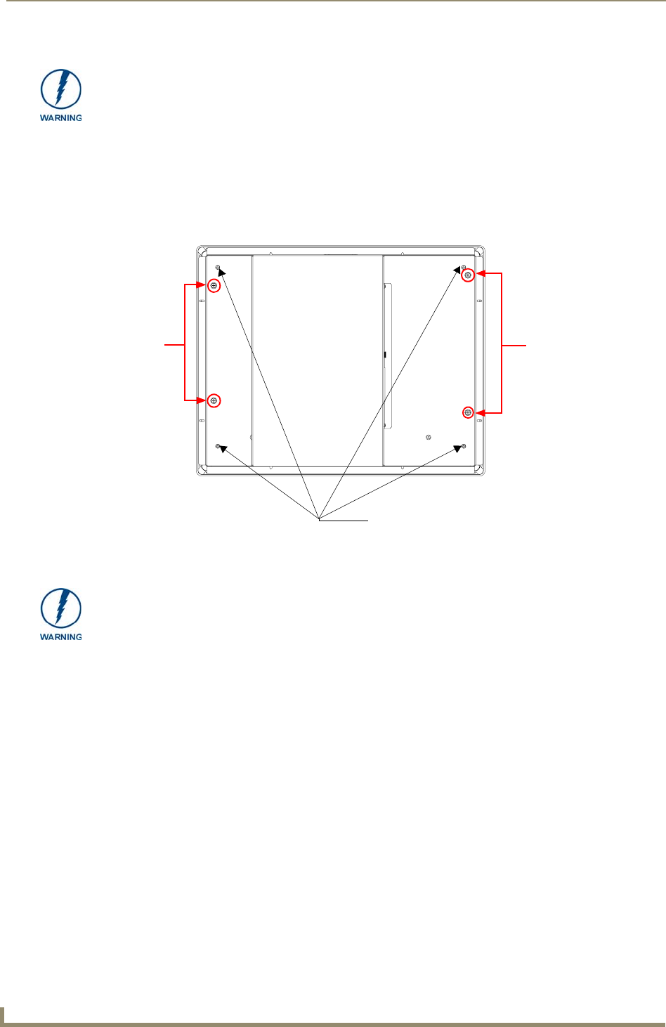
DO NOT REMOVE THE PANEL SECURING SCREWS. These screws secure the
LCD to the metallic casing underneath.
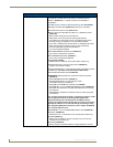
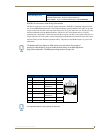
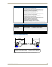
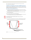
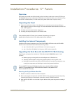
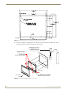
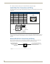
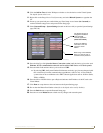
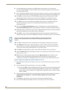
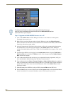
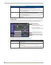
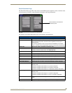
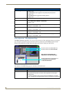
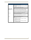
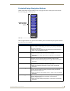
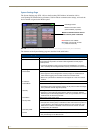
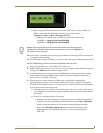
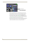
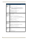
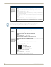
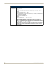
FIG. 51 Location of the attachment screws on the NXD back box
Unscrew these four Housing Screws to
DO NOT
these
DO NOT REMOVE
REMOVE
panel
securing
screws
these panel
securing screws
remove the back box. These make direct
contact with the black outer housing.
DO NOT REMOVE THE FOUR PANEL SECURING SCREWS. These screws secure
the LCD to the metallic casing underneath.