


Installation Procedures: 17" Panels
73
VG-Series Modero Touch Panels
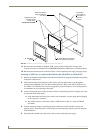
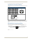
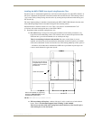
Cable Installation for the MP-TP17 Back Box
1.
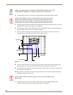
Connect the cable connectors (RJ-45, Ethernet, and any other audio/video wiring) to their respective
locations along the side of the touch panel.
2. Use the tie-wrap (45-0009A) to wrap the cables together inside the VESA Mount enclosure. This
cable tie is used to insure the cable will not pull through or work itself through the new larger strain
relief grommet (45-0032-01) over time.
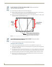
3. Thread the incoming cables through the hole on the rear plastic cover and then through the strain
relief grommet.
4. Slide the grommet along the cable and securely insert it into the opening on the rear plastic cover
(FIG. 52).
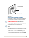
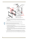
Finalizing the installation
1.
Gently place the rear plastic cover over the NXD panel (with LCD and MB-TP17 back box).
2. Insert the protruding cables, coming out from the opening on the rear plastic cover, into the open
strain relief grommet.
3. Allow some slack/length on these cables as a service loop. This service loop provides enough cable
length so you can later remove the NXD (with connected cables) from the rear plastic cover.
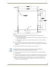
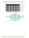
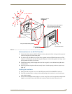
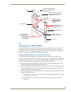
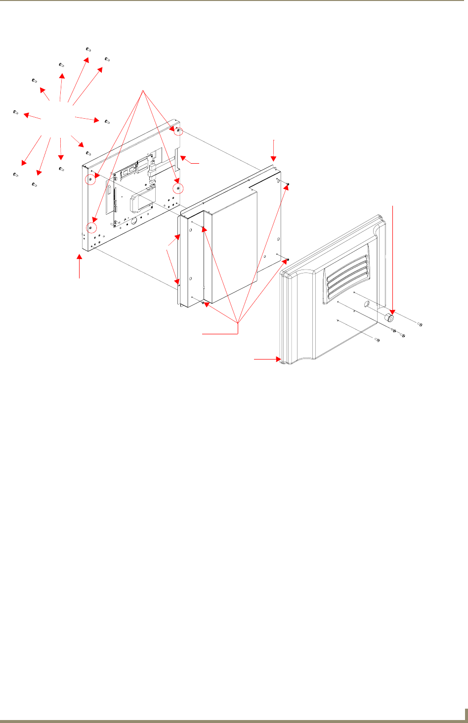
FIG. 52 Location of the attachment screws on the NXD back box and VESA housing
Four (#8-32) screws
Internal panel casing
MB-TP17 back box
Ten
Rear plastic cover
(60-0033-50)
Connector
Four (pan-head) Housing Screws
Securing
(62-0033-50)
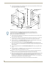
Strain relief grommet
(Clip facing up)
Rim of the strain relief grommet
should lie flush against enclosure
opening
hole locations
(2 on each side)
securing
DO NOT REMOVE
screws
#6-32