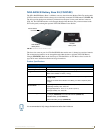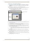
Installation Procedures: 12" and 15" Panels
60
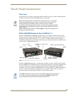
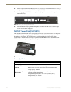
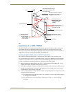
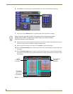
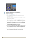
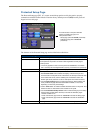
VG-Series Modero Touch Panels
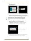
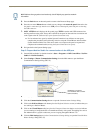
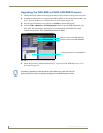
4. Test the incoming wiring by connecting the panel connections to their terminal locations and
applying power. Verify the panel is receiving power and functioning properly to prevent repetition
of the installation.
5. Disconnect the terminal end of the power cable from the connected power supply.
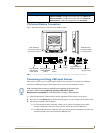
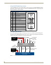
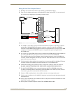
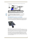
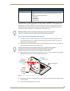
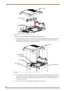
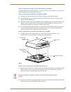
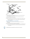
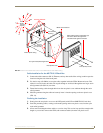
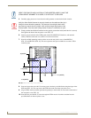
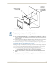
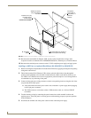
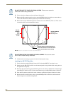
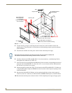
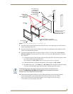
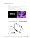
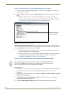
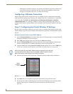
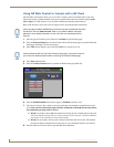
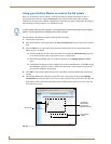
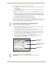
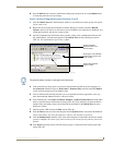
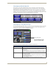
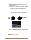
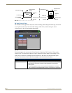
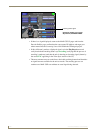
6. Carefully slide the main unit (B in FIG. 39) into the conduit box, so that all Mounting Tabs lie flush
against the conduit box (C in FIG. 39).
7. Insert and secure the four securing #4-40 Mounting Screws into their corresponding holes located
along the sides of the NXD (FIG. 38 and FIG. 39).
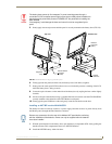
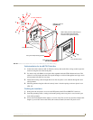
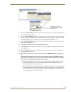
8. Place the magnetic faceplate (A in FIG. 39) back onto the main NXD unit (B in FIG. 39). Make sure
to align the Microphone, Light, and PIR Motion sensor locations to their respective openings on the
front bezel/faceplate.
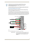
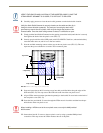
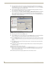
9. Reconnect the terminal RJ-45, Ethernet, USB, and any optional audio/video wiring to their
respective locations (outside the conduit box) on either the NXA-AVB/RGB Breakout Box, Ethernet
port, or NetLinx Master.
10. Reconnect the terminal power connector on the 12 VDC-compliant power supply and apply power.
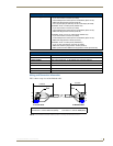
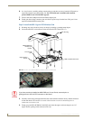
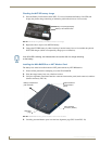
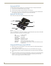
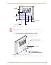
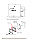
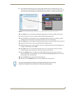
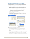
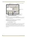
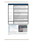
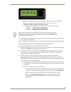
Installing the NXD into drywall using Expansion Clips
Expansion clips are mounted through the four oval holes located at the top and bottom of the panel. As
the screw is tightened, the clip bends toward the insertion hole and into the wall. This bending creates a
"grip" on the wall by either pressing onto the wall or by securing the drywall between the housing and
the drywall clip.
The most important thing to remember when mounting the NXD is that the outer frame (Mounting Tabs)
must be installed flush against the mounting surface.
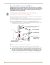
It is recommended that you cutout the surface slightly smaller than what is outlined in the
installation drawings so that you can make any necessary cutout adjustments.
1. Prepare the area by removing any screws or nails from the drywall before beginning the cutout
process.
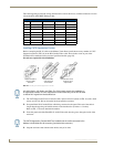
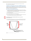
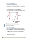
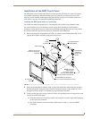
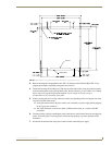
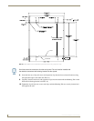
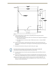
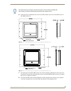
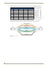
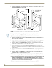
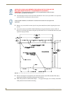
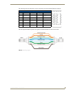
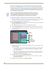
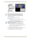
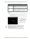
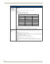
2. Cut out the surface for the 12-inch Wall Mount using the dimensions shown in FIG. 40 and for the
15-inch Wall Mount using the dimensions shown in FIG. 41. Be sure to cut out the four notches
along the top and bottom areas to accommodate the four drywall expansion clips (provided).
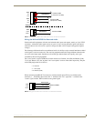
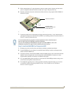
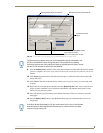
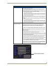
Don’t disconnect the connectors from the touch panel. The unit must be installed with
the attached connectors before being inserted into the conduit box.