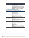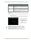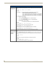
Installation Procedures: 17" Panels
80
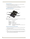
VG-Series Modero Touch Panels
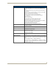
2. Locate the edges of the two studs used in this installation. The location of the NXD is site dependant
and could involve notching more than one beam.
3. Remove any screws/nails from the drywall, along the notched beam, before beginning the cutout
process.
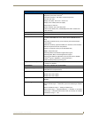
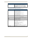
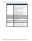
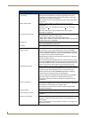
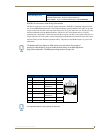
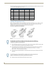
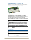
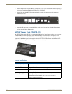
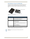
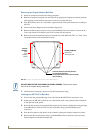
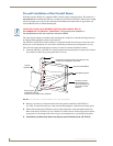
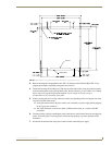
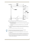
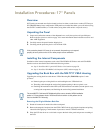
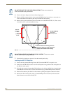
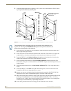
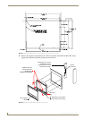
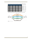
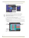
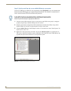
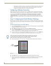
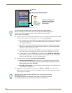
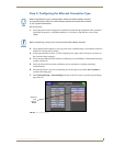
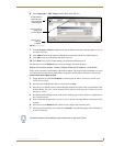
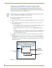
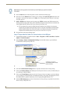
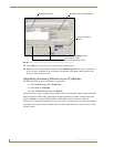
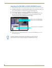
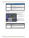
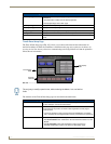
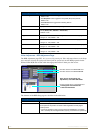
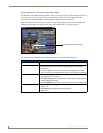
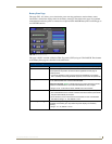
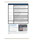
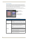
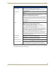
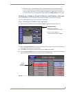
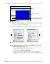
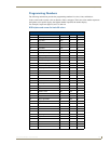
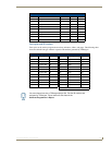
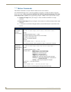
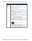
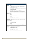
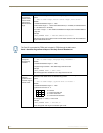
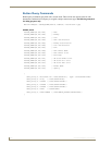
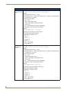
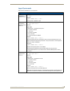
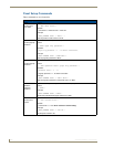
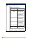
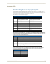
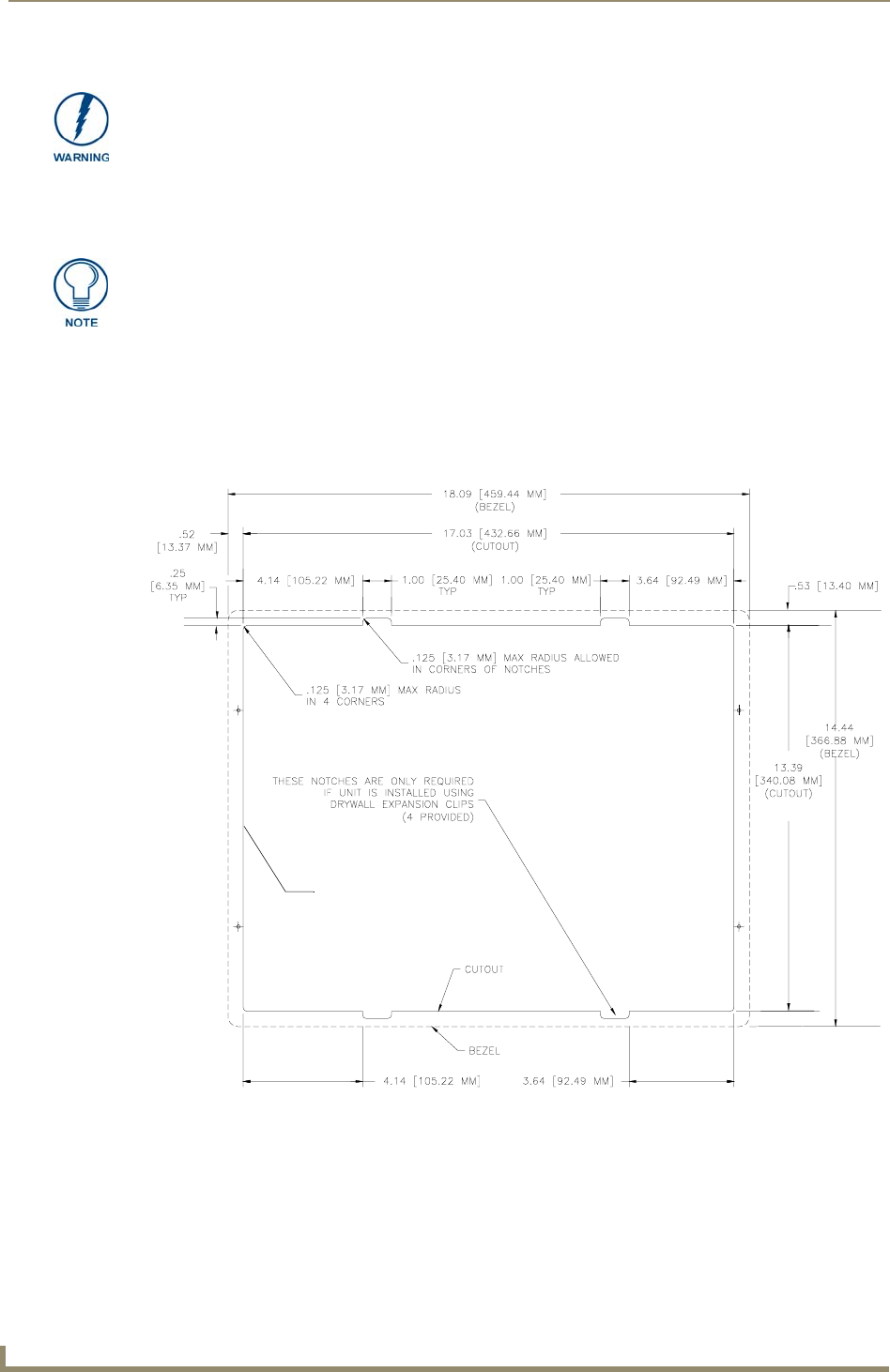
4. Cut out the surface for the NXD-1700VG Wall Mount using the dimensions shown in FIG. 59.
Be sure to cut out the four notches along the top and bottom areas to accommodate the four drywall
expansion clips (provided).
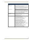
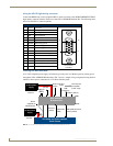
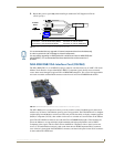
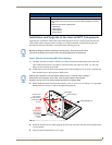
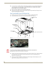
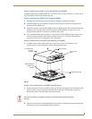
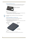
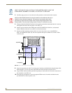
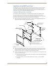
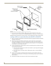
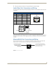
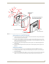
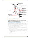
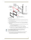
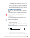
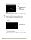
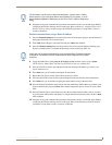
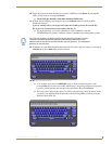
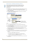
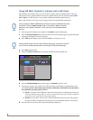
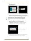
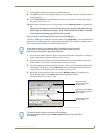
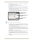
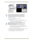
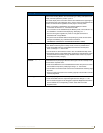
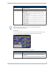
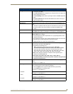
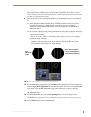
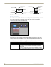
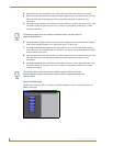
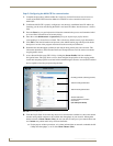
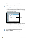
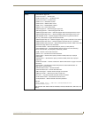
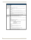
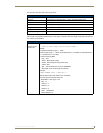
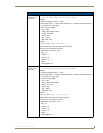
5. Remove the magnetic faceplate/bezel (A in FIG. 60) from the main NXD unit (B in FIG. 60) by
gripping the faceplate and pulling with gentle outward force.
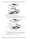
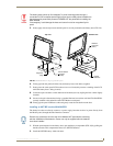
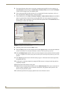
6. Follow the procedures outlined within Steps 1 - 5 on page 42 thru page 43 to carefully reinstall the
LCD panel back into the back box housing.
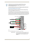
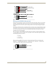
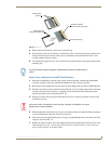
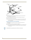
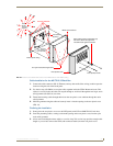
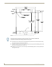
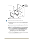
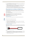
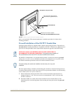
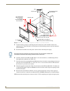
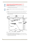
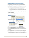
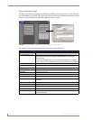
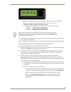
INSTALLER: LEAVE A GAP BETWEEN THE SURFACE OF THE STUD AND THE
BACK BOX MOUNTING RIDGE TO ACCOMMODATE THE DRYWALL/
SHEETROCK. This gap allows the installation of the drywall/sheetrock after the back
box has been mounted onto the beams.
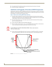
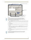
In this sample installation, the left beam is notched and the back box rests against the
right beam.
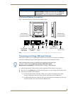
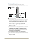
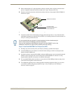
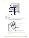
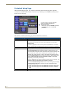
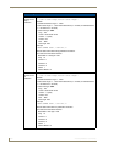
FIG. 59 NXD-1700VG Wall Mount panel dimensions using expansion clips
*
*
* Top notches are
not symmetrical
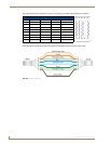
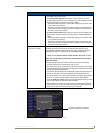
Left Side
Right Side
Connectors