


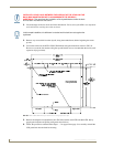
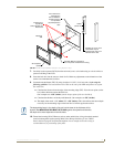
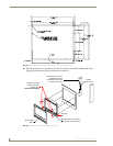

Installation Procedures: 17" Panels
88
VG-Series Modero Touch Panels
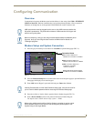
3. Verify the connection of the 2-pin 3.5 mm mini-Phoenix to the power supply.
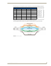
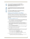
Audio/Video Port: Connections and Wiring
The following table shows the signal and pinout/pairing information used on the RJ-45 Audio and Video
connections.
Refer to the Installing CAT5 Suppression Ferrites section on page 30 for detailed information on how to
install the necessary number of CAT5 Suppression Ferrites on the Black A/V RJ-45 cable connected to
the panel.
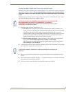
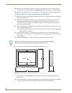
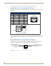
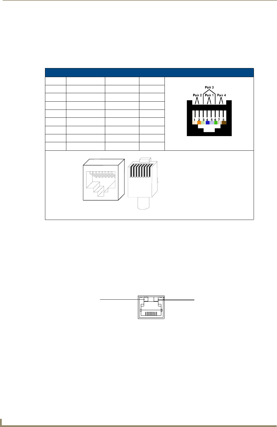
Ethernet/RJ-45 Port: Connections and Wiring
FIG. 65 describes the blink activity for the Ethernet 10/100 Base-T RJ-45 connector and cable. The
Ethernet cable is connected to the rear of Table Top and side of the Wall Mount panels.
Audio/Video RJ-45 Pinout Information
Pin Wire Color Function Polarity
1 Orange/White Right Audio In +
2 Orange Right Audio In -
3 Green/White Video In -
4 Blue Mic Out -
5 White/Blue Mic Out +
6 Green Video In +
7 White/Brown Left Audio In +
8 Brown Left Audio In -
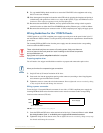
FIG. 65
Ethernet connector (showing communication and connection LEDs)
TIA 568B
1 2 3 4 5 6 7 8
1 2 3 4 5 6 7 8
RJ-45 connector - pin configurations
(female) (male)
ETHERNET
10/100
A L
A - Activity LED (yellow)
lights when receiving or
transmitting Ethernet
data packets
L - Link LED (green) lights when
the Ethernet cables are connected
and terminated correctly.