


Installation Procedures: 12" and 15" Panels
63
VG-Series Modero Touch Panels
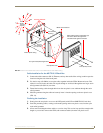
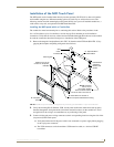
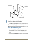
11. Place the magnetic faceplate (A in FIG. 42) back onto the main NXD unit (B in FIG. 42). Make sure
to align the Microphone, Light, and PIR Motion sensor locations to their respective openings on the
front bezel/faceplate.
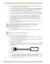
12. Connect the terminal RJ-45, Ethernet, USB, and any optional audio/video wiring to their respective
locations on either the NXA-AVB/RGB Breakout Box, Ethernet port, or NetLinx Master.
13. Reconnect the terminal power connector on the 12 VDC-compliant power supply and apply power.
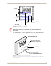
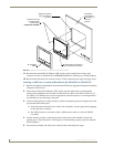
Installing the NXD into a Flat Surface using #4 screws
Mounting screws (#4, not included) are secured through circular holes located at the left and right sides
of the NXD panel. The most important thing to remember when mounting the NXD is that the
outer frame (Mounting Tabs) must be installed flush against the mounting surface.
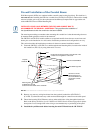
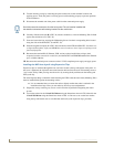
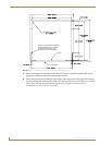
It is recommended that you cutout the surface slightly smaller than what is outlined in the
installation drawings so that you can make any necessary cutout adjustments.
1. Prepare the area by removing any screws or nails from the surface before beginning the cutout
process.
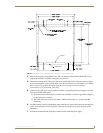
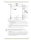
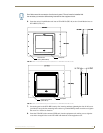
2. Cut out the surface for the 12-inch Wall Mount using the dimensions shown in FIG. 43 and for the
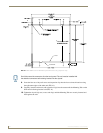
15-inch Wall Mount using the dimensions shown in FIG. 44.
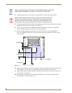
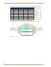
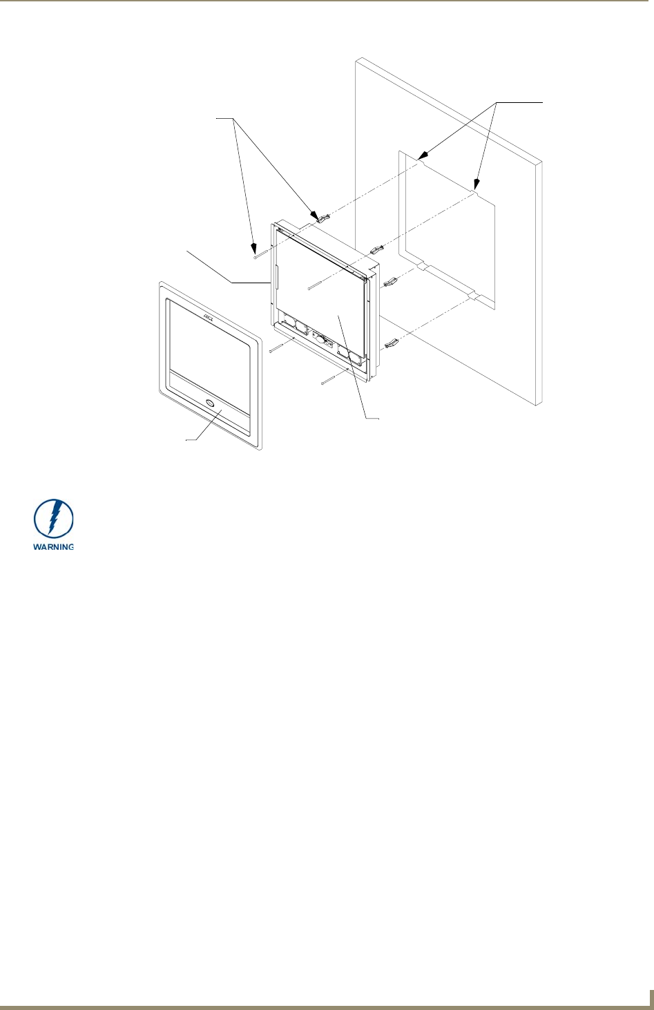
FIG. 42 Wall Mount panel (NXD) installation configuration for drywall surfaces
B - Main NXD unit consists of
Install the four drywall
clip sets (included)
into these holes
the touch panel and housing
4 notches are
required if the
unit is installed in
drywall using the
four (4) provided
drywall expansion
A - Faceplate
(bezel)
clips
Mounting Tab
The drywall clip set must be re-ordered from AMX if the drywall clip is bent
accidentally during an installation or removed during a re-installation.