Installation Procedures: 17" Panels
74
VG-Series Modero Touch Panels
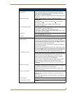
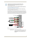
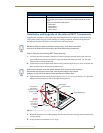
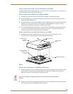
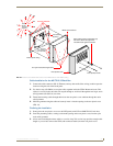
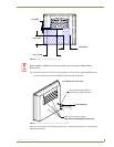
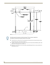
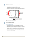
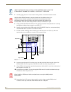
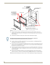
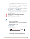
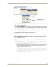
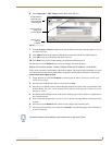
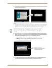
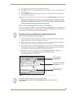
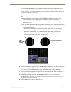
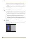
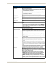
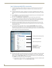
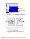
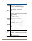
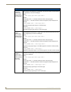
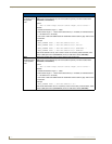
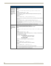
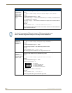
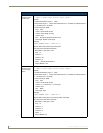
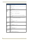
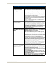
4. Carefully apply pressure to close the strain relief grommet over the desired cable location.
5. Firmly push the Strain Relief Grommet into the opening (toward the inside) until the rim is securely
flush against the back of the rear plastic cover (FIG. 53).
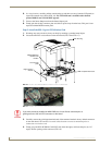
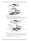
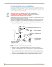
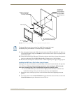
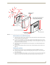
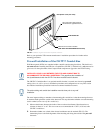
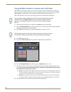
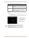
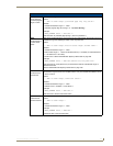
6. Securely grasp both sides of the NXD panel (with LCD, MB-TP17 back box, and attached cables),
rotate the entire unit over, and lie it on a flat level surface.
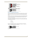
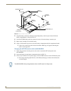
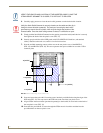
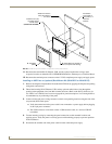
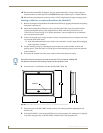
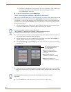
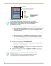
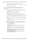
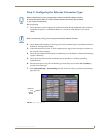
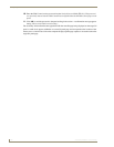
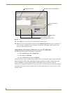
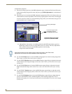
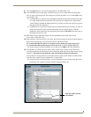
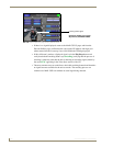
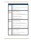
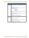
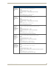
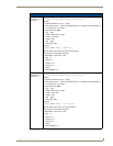
7. Note the available mounting contact surface area on the rear plastic cover (FIG. 53). This area
represents the space available for use with a VESA connector plate.
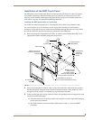
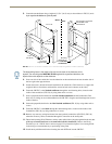
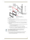
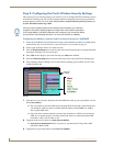
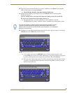
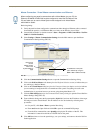
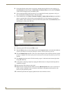
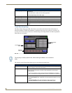
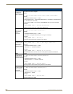
8. Insert and secure the ten #6-32 securing screws into their pre-drilled holes along the edges of the
NXD unit (FIG. 52). This step secures the NXD unit to the rim of the rear plastic cover.
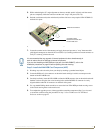
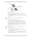
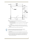
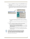
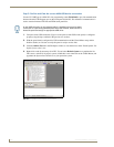
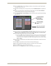
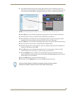
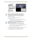
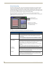
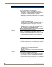
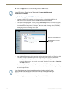
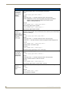
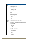
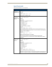
9. Align a VESA mount connector (purchased separately) to the four #8-32 screw holes on the back of
the rear plastic cover (FIG. 53).
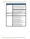
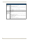
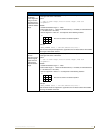
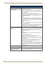
10. Insert the four provided #8-32 screws through the VESA mount’s four holes and then into the pre-
drilled holes on the rear plastic cover.
11. Secure these four #8-32 screws to the rear plastic cover by using a grounded Phillips-head
screwdriver. This step secures the VESA mount to the rear of the panel.
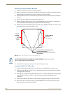
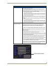
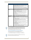
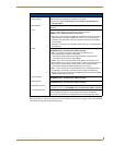
VERIFY THE LENGTH AND LOCATION OF THE INSERTED CABLES. ONCE THE
STRAIN RELIEF GROMMET IS CLOSED, IT IS DIFFICULT TO RE-OPEN.
Verify the Strain Relief Grommet is securely closed over the cables and the clip is
facing the correct direction (upwards). The process of securing the strain relief
grommet may require the use of pliers. Also verify the length and location of the
inserted cables. Once the strain relief grommet is closed, it is difficult to re-open.
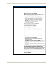
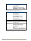
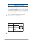
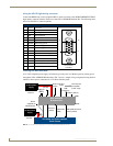
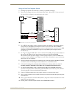
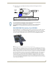
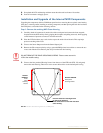
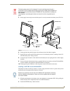
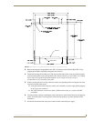
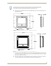
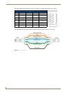
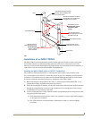
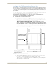
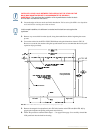
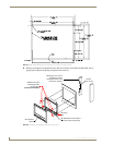
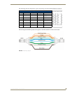
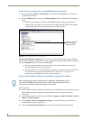
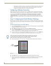
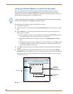
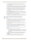
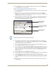
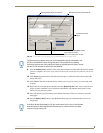
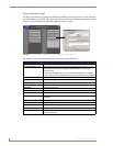
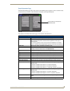
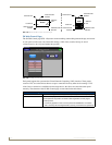
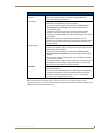
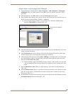
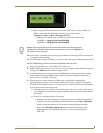
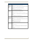
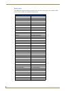
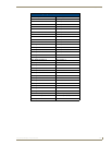
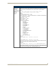
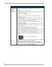
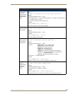
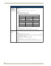
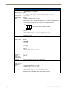
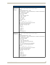
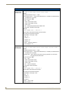
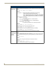
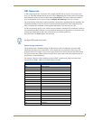
FIG. 53 MB-TP17 Mounting contact surface area
.83[21MM]
1.84[47MM]
4.06[103MM]
3.83[97MM]
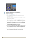
When installing a VESA mount to the rear plastic cover, use only the AMX provided
#8-32 screws.