


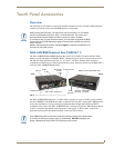

Touch Panel Accessories
24
VG-Series Modero Touch Panels
Wiring the NXA-AVB/RGB for Unbalanced Audio
Most domestic audio equipment has unbalanced audio inputs and outputs. This means that the audio
output (left, right, or mono) appears on a single wire, and is referenced to "0 V" or "Ground". Typical
connectors used are RCA "phono" connectors, DIN plugs/sockets, and 0.25" (6.3mm) or 3.5mm jack
plugs/sockets.
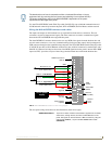
Unbalanced audio is adequate for most domestic environments and for line-level signals in a typical
broadcast studio. Problems may occur if the signals are carried over long distances, especially if the
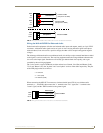
source and destination have separate main supplies. Use the following wiring drawing (FIG. 5) to
configure an unbalanced audio connection.
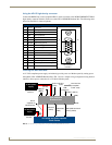
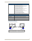
When using unbalanced audio for the AUDIO IN connector (FIG. 5), the "-" and the "GND" terminals
should be connected together and then connected to the GND of the unbalance audio signal. When
connecting to an unbalanced audio input from the MIC OUT connector (FIG. 5), wire the "+" terminal to
the signal input, and the "GND" terminal to the signal ground.
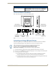
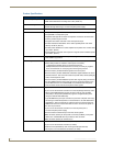
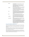
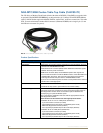
• MIC OUT: 4-pin mini-Phoenix connector, divided into GND, OUT-, and OUT+
terminal connectors.
An example of this cable is to strip the terminal ends of a 3.5mm
mini-jack and insert them into their respective locations on the Mic
Out port. This signal can be fed as a Line Level In to either an
amplifier or an AMX VOL card.
Either a balanced (+, -, and GND) or unbalanced (+ and GND) audio
signal can be connected to this output.
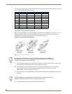
• AUDIO IN: 6-pin 3.5 mm mini-Phoenix connector, divided into left and right audio
channels. Each channel is divided into GND, IN+, and IN- terminal
cable connectors (2 sets of 3 for each channel).
An example of this cable is to strip the ends of 2 RCA audio cables
and insert them into their respective locations on the Audio In port.
Either a balanced (+, -, and GND) or unbalanced (+ and GND) audio
signal can be connected to this input.
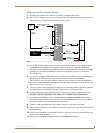
•USB: Type-B USB device port input connector for pass-thru computer
control. This port provides two-way signal between the keyboard and
mouse (connected to the rear/side USB connectors on the Modero
panel) through the front RGB connector on the breakout box, out the
rear USB Type-B connector, and then to/from the connected
computer.
•PWR: 2-pin 3.5 mm mini-Phoenix connector that connects to a
12 VDC-compliant power supply. This port can be used to provide
power to a Modero panel by sending it through the NXA-AVB/RGB
(rear power connector through to the front power connector).
• ETHERNET: RJ-45 connector routes data to the G4 panel through the front
Ethernet port. These connections use a standard CAT5 Ethernet
cable to provide communication between the target panel, box, and
Master.
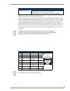
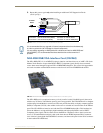
• Video In BNCs: Feeds either Composite/S-Video Luma or S-Video Chroma signals
into the NXA-AVB/RGB. This feed is then redirected out to a Modero
panel through the front Audio/Video CAT5 port.
Note: Although the NXA-AVB/RGB Breakout Box can accept either a
Composite or S-Video input signal type, only one input source can be
used at a time. This unit does not auto-detect the incoming signal
type. Using S-Video would require a cable split and a simultaneous
connection to both the COMP/Y and C connectors (which would
prevent an additional Composite signal from being fed into the unit).
A user should not try to connect two Composite video signal cables to
the COMP/Y and C connectors.